Configuration Instructions for Modbus/TCP to CAN converter
4. Configuration instructions
4.1 Basic parameter configuration
The GCAN-205 converter can be configured by using the "GCAN205-ModbusTcp-CAN-configV3.CH" software, including the basic parameters such as operating mode, working port, target port, target IP, CAN operating mode, CAN baud rate.
4.1.1 Connect the GCAN-205 converter to the computer
1. Power on the converter, and connect the converter to the computer with a network cable
2. Open the "GCAN205-ModbusTcp-CAN-configV3.CH" software

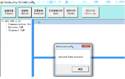
"Connect" - connect equipment
"Upload" - read out the configuration information in the converter
"DownLoad" - download the configuration information to the converter Flash
"Open" - open and read the configuration information file in the PC
"SaveAs" - save the configuration information file to your computer
3. Click "Connect" and enter the IP address of GCAN-205
4. After connecting, click "UpLoad" to upload the parameters of the converter to the computer. After that, the following information will be displayed

4.1.2 CAN baud rate setting
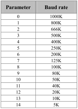
"CAN Baudrate" can set the baud rate of the CAN-Bus, the corresponding table is as follows:

4.1.3 Ethernet address settings
"IP Address" - set the IP address of the converter
"Subnet Mask" - set the subnet mask
"GateWay" - set the communication gateway
When the parameter is modified, the corresponding unit becomes red
4.2 Receive CAN data mapping table
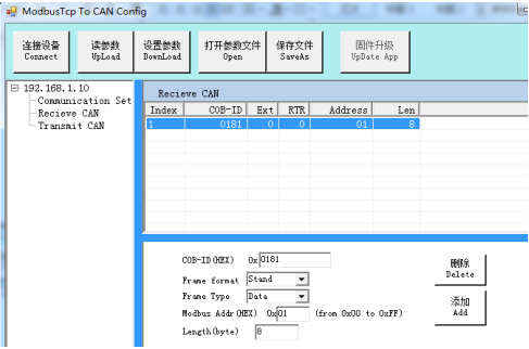
Click "Receive CAN" in the left side of the interface to display the following interface.
 COB-ID: set the frame ID of the CAN-Bus
Frame Format: set the frame format
Frame Type: set the frame type
Modbus address: set the Modbus register first address
Length: CAN frame data length, the maximum value of 8
4.3 Transmit CAN data mapping table
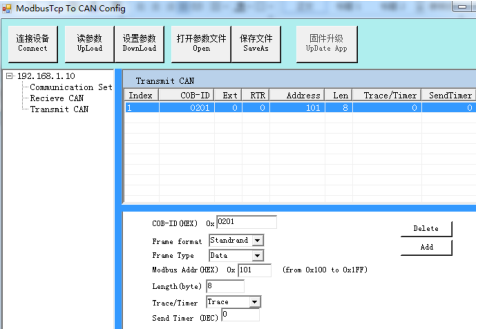
Click "Transmit CAN" project and add data mapping group, at least 32 groups.
 COB-ID: set the frame ID of the CAN-Bus
Frame Format: set the frame format
Frame Type: set the frame type
Modbus Address: set the Modbus register first address
Length: CAN frame data length, the maximum value of 8
Trace mode: If GCAN-205 receives data from Modbus master,it will transmit the data to the CAN-Bus.
Timer mode: at intervals, GCAN-205 transmit the data to the CAN-Bus.The time interval can be set with decimalism below, with unit ms.
4.4 Download to the Flash of GCAN-205
When the configuration is complete, users can click on the "DownLoad" to write data into the converter Flash.When the data is written successfully, you need to re-power to enable the new settings.
4.5 Save GCAN-205 converter parameters
Configuration parameters can be saved to PC by "SaveAs". The configuration file can be opened again.
NOTE: after the configuration is downloaded successfully, you need to re-power the converter to enable the new configuration.
4.1 Basic parameter configuration
The GCAN-205 converter can be configured by using the "GCAN205-ModbusTcp-CAN-configV3.CH" software, including the basic parameters such as operating mode, working port, target port, target IP, CAN operating mode, CAN baud rate.
4.1.1 Connect the GCAN-205 converter to the computer
1. Power on the converter, and connect the converter to the computer with a network cable
2. Open the "GCAN205-ModbusTcp-CAN-configV3.CH" software

"Connect" - connect equipment
"Upload" - read out the configuration information in the converter
"DownLoad" - download the configuration information to the converter Flash
"Open" - open and read the configuration information file in the PC
"SaveAs" - save the configuration information file to your computer
3. Click "Connect" and enter the IP address of GCAN-205
4. After connecting, click "UpLoad" to upload the parameters of the converter to the computer. After that, the following information will be displayed

4.1.2 CAN baud rate setting
"CAN Baudrate" can set the baud rate of the CAN-Bus, the corresponding table is as follows:

4.1.3 Ethernet address settings
"IP Address" - set the IP address of the converter
"Subnet Mask" - set the subnet mask
"GateWay" - set the communication gateway
When the parameter is modified, the corresponding unit becomes red
4.2 Receive CAN data mapping table
Click "Receive CAN" in the left side of the interface to display the following interface.

Frame Format: set the frame format
Frame Type: set the frame type
Modbus address: set the Modbus register first address
Length: CAN frame data length, the maximum value of 8
4.3 Transmit CAN data mapping table
Click "Transmit CAN" project and add data mapping group, at least 32 groups.

Frame Format: set the frame format
Frame Type: set the frame type
Modbus Address: set the Modbus register first address
Length: CAN frame data length, the maximum value of 8
Trace mode: If GCAN-205 receives data from Modbus master,it will transmit the data to the CAN-Bus.
Timer mode: at intervals, GCAN-205 transmit the data to the CAN-Bus.The time interval can be set with decimalism below, with unit ms.
4.4 Download to the Flash of GCAN-205
When the configuration is complete, users can click on the "DownLoad" to write data into the converter Flash.When the data is written successfully, you need to re-power to enable the new settings.
4.5 Save GCAN-205 converter parameters
Configuration parameters can be saved to PC by "SaveAs". The configuration file can be opened again.
NOTE: after the configuration is downloaded successfully, you need to re-power the converter to enable the new configuration.


