
Modbus/TCP to CAN converter Usage Instructions_GCAN
3. Connection and use
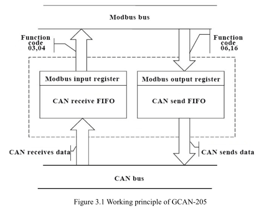
The working principle of GCAN-205 is shown in Figure 3.1.
3.1 Configure with PC connections
The GCAN-205 converter uses a 24V DC power supply. By using the "GCAN205-ModbusTcp-CAN-configV3.CH" software, the GCAN-205 converter can configure the working model and the parameter. GCAN-205 only supports communication between Modbus / TCP-CAN, other protocols are not supported.
3.1.1 Restore the factory Settings
GCAN-205 converter factory IP: 192.168.1.10. If users have changed the IP, users can operate the DIP switch to reset the parameters
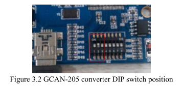
Operation method: first open the converter shell to find the switch shown in Figure 3.2. Second switch the No. 2 to "ON", then supply the power, waiting for 3 seconds. After the "SYS" indicator flashing, turn off the power and switch back to "OFF". Now,
the converter has been restored to the factory default state, the system factory IP:
192.168.1.10.
Please note: after the converter has been reset, all parameter settings and mapping table settings will be cleared. Please be careful.
3.1.2 Change the IP address for PC
PC IP and GCAN-205 IP must be in the same network segment.
For example: converter IP: 192.168.1.10, PC IP: 192.168.1.1.
Please note: PC IP can not be the same as the converter IP.
3.2 Connect to Ethernet
The ethernet interface of the GCAN-205 converter integrates a 10 / 100M adaptive ethernet chip. The converter conforms to the ethernet standard protocol specification.
3.3 Connect to CAN-Bus
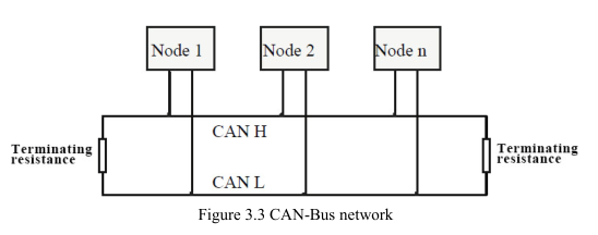
In practical use, users only need to connect the CAN_H to CAN_H and CAN_L to CAN_L, then communication can be realized.
The CAN-Bus network adopts topological structure, only the two furthest terminal need to connect 120Ω terminal resistance between CAN_H and CAN_L. For branch connection, its length should not be more than 3 meters. CAN-Bus nodes connection as shown in figure 3.3.
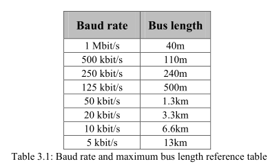
 Note: CAN-Bus using ordinary twisted pair. The relationship between the bus length and baud rate is shown in Table 3.1.
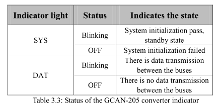
3.4 System LED
GCAN-205 converter with one SYS indicator, one DAT indicator. More functions are shown in table 3.2.
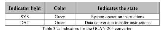
After power on the converter, the SYS indicator light indicates that power is being supplied and the system is initializing; otherwise, it indicates power failure or an error occurred.
If the bus has data transmission, DAT indicator will flash.
The working principle of GCAN-205 is shown in Figure 3.1.
3.1 Configure with PC connections
The GCAN-205 converter uses a 24V DC power supply. By using the "GCAN205-ModbusTcp-CAN-configV3.CH" software, the GCAN-205 converter can configure the working model and the parameter. GCAN-205 only supports communication between Modbus / TCP-CAN, other protocols are not supported.
3.1.1 Restore the factory Settings
GCAN-205 converter factory IP: 192.168.1.10. If users have changed the IP, users can operate the DIP switch to reset the parameters
the converter has been restored to the factory default state, the system factory IP:
192.168.1.10.
Please note: after the converter has been reset, all parameter settings and mapping table settings will be cleared. Please be careful.
3.1.2 Change the IP address for PC
PC IP and GCAN-205 IP must be in the same network segment.
For example: converter IP: 192.168.1.10, PC IP: 192.168.1.1.
Please note: PC IP can not be the same as the converter IP.
3.2 Connect to Ethernet
The ethernet interface of the GCAN-205 converter integrates a 10 / 100M adaptive ethernet chip. The converter conforms to the ethernet standard protocol specification.
3.3 Connect to CAN-Bus
In practical use, users only need to connect the CAN_H to CAN_H and CAN_L to CAN_L, then communication can be realized.
The CAN-Bus network adopts topological structure, only the two furthest terminal need to connect 120Ω terminal resistance between CAN_H and CAN_L. For branch connection, its length should not be more than 3 meters. CAN-Bus nodes connection as shown in figure 3.3.
3.4 System LED
GCAN-205 converter with one SYS indicator, one DAT indicator. More functions are shown in table 3.2.
If the bus has data transmission, DAT indicator will flash.
