
The solution for debug Modbus to CAN device
The solution for debug Modbus to CAN device
GCAN-204 is our GCAN's Modbus RTU to CAN device, many engineers can not receive data at Modbus side when debugging. So let’s look at how to solve this problem
Here are the common reasons for not receiving data
The main reasons for not receiving data are: serial port configuration or wiring error, Modbus software usage error, CAN side configuration or wiring error. Since our equipment is a standard Modbus slave device, serial port configuration or wiring errors and debug software errors are easy to find and resolve.
However, the problem at the CAN side is more complicated. It is necessary to check whether there is an error in the wiring. The client has no data to issue or whether there is an interaction protocol to trigger, whether the actual data ID and configuration are matched.
Here is a case
Kim Tae Hwan from a Korean university, need to connect three sensors with CAN interface with GCAN-204. He can enter the configuration software and use the Modbus debugging software, but he can't receive the data from the sensor. What’s the problem.
Since Kim Tae Hwan can enter the configuration software, and use the Modbus debugging software. We can judge that there is no problem with the physical layer and configuration of the serial port of the device.
This is a typical CAN configuration and wiring problem. We asked Kim for the wiring environment at CAN side, whether the protocol of the CAN side of the sensor is known, and a screenshot of the configuration software is requested.
Kim Tae Hwan replied that two of the sensors of the same model are J1939, and the other model has an interactive protocol. The baud rate of the device is 250K. All three sensors are connected to the CAN side of CGAN-204. The configuration is configured according to the sensor manual.
From this we can determine that we are not sure if the configuration is correct.
After excluding the physical layer of the CAN side, it is recommended Kim Tae Hwan buy a USBCAN-II Pro analyzer to verify and detect the real data sent by the sensor. After the final verification by Kim Tae Hwan, the reazon is the two sensors of the same model have the same node number, after the two devices are connected together, only two alarm data are sent, and they no longer work. It does not match the CAN data ID during normal operation configured according to the manual.
This is caused by the ID of the typical CAN end configuration not matching the actual received data ID. After changing the node number of one sensor, the two sensors can Normal operation, according to the data ID received by the USBCAN analyzer, after reconfiguration, the data from two sensors of the same model was successfully received using Modbus software.
When debugging a sensor with an interactive protocol, Kim Tae Hwan first uses the USBCAN analyzer to debug. After the debugging is successful, after the correct parameters are configured to GCAN-204, the feedback phenomenon is that the device's DAT light flashes three times, but Modbus poll The software did not receive the data. Below is a video of Kim Tae Hwan's feedback.
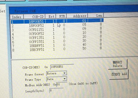
According to the video, you can see that the DAT light is flashing, indicating that there is data passing through the device. Three flashes, indicating that the configuration trigger is successful and there is data return. Judging is a typical Modbus software usage problem, combined with the configuration screenshot provided by Kim Tae Hwan, the feedback data ID binding register address is 20, 30, 40, 50, this is the hexadecimal address, and Modbus software The address is in decimal, resulting in a read error, changing the read register address and changing the number of read registers from 10 to 30, the data was successfully read.
1. The physical layer of the serial port is correct.
The phenomenon is that you can enter the configuration software. Here you need to check the wiring of the device serial port, the port number, and whether the device is in configuration mode.
2. To determine the configuration
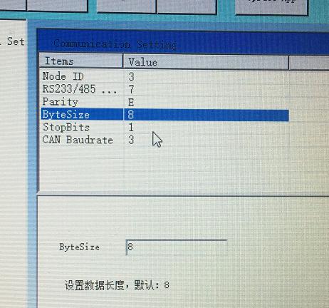
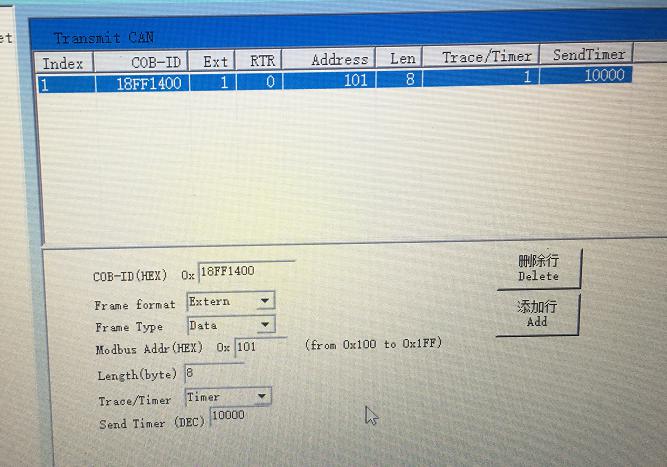
The configuration needs to understand the principle of our device. It is a standard Modbus RTU slave to CAN device. The device connects two distinct buses together by binding the register address of the Modbus and the CAN data ID. Ensure that the Modbus parameter configuration and the CAN terminal baud rate configuration are correct, and the mapping relationship between the CAN ID and the Modbus register address should be correctly configured. And to ensure that our GCAN-204 device can receive, so when you do not understand or are uncertain about the use of CAN devices, you may wish to purchase a USBCAN analyzer for debugging and configuration. After the configuration is correct, you can get twice the result with half the effort. The following figure shows the correct configuration after networking.
3.Determine the physical layer of the CAN end.
Check the wiring, resistance, baud rate, etc. The phenomenon is whether the DAT lamp is shining and whether the data passes.
4.Use Modbus poll software
According to the configuration, the software is called, and the software is used to read or write to the configured register address to perform the transmission and reception test.
Welcome to contact us, if you want to know more about GCAN and GCAN products.
Our Tel: +86 17742765166.
Email: seven.gcan@gmail.com
:GCAN-201")


