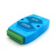
Description of the features of usbcan-obd
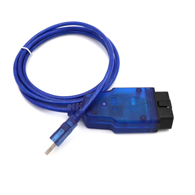
The usbcan-obd product is a professional analysis tool for developing, testing, maintaining and managing CAN-bus networks. It is versatile and powerful.
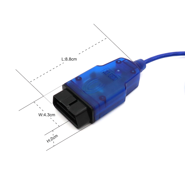
This product adopts USB, OBD-II interface, has the characteristics of small size and plug and play. It is very suitable for collecting data on site and detecting network status. It is also a good choice for portable system users.
This product supports Win98 / Me / 2K / XP and other 32-bit operating systems and win7 and other 64-bit operating systems, can run the company's new upgrade EcanTools software.
This product uses advanced electromagnetic isolation technology (non-conventional optocoupler isolation) to ensure stable performance and avoid damage caused by electrical surges, which enhances the reliability of the equipment in harsh environments.
The same computer (PC) can run multiple USBCAN devices at the same time without mutual interference, and can test and debug multiple CAN devices.
Function description:
1. Data transmission function:
General transmission mode: set ID, data length, send data content, set extended frame, set remote frame can set cyclic transmission data, set interval time, set the number of cyclic transmissions, set ID auto increment, can set to start sending immediately.
List sending mode: After editing the sending frame, you can add the data to the sending list. The sending list can add at least 100 frame data. The data in the sending list can be sent at the same time. The CAN Pro software sending list can be saved.
Program programming function: The program can be programmed by CAN to send files to the devices on the CAN bus, such as programming the car ECU (very useful for users of automotive electronics).
Send data in batches: Users can edit multiple packets to be sent beforehand, and then set the transmission interval to send multiple packets continuously (this function is very useful if debugging CAN devices with timing requirements).
Frame statistics function: It has the same statistical function as the German PEAK PCAN software interface, can display the functions according to the same frame ID, and can display the real-time data of the same ID frame in real time, the same ID frame period (interval time) and the same ID frame. Counting (this feature is very useful for CAN devices with precise timing requirements and can be accurate to 0.01ms).
Frame storage function: In the receiving data window, the receiving data frame, the sending data frame, the event frame (corresponding error of CAN bus) can be displayed at the same time, and the received data can be stored as a text file.
Automatic identification of baud rate (new): to be a bus device developer and intercept the data of existing CAN devices, the basic problem encountered is that the baud rate does not match, do not know the wave set by their own microcontroller Is the rate correct? I don't know what the porter used on the existing CAN device is? Now it can be solved, through the ECanTools software, you can automatically identify the baud rate on the bus in normal operation. See the ECAN tool baud rate automatic identification for details.
With bus diagnostic function, it can detect bus error frame and bus arbitration lost bit, and realize a more comprehensive CAN bus analysis.
CAN bus status display: Indicates the current CAN bus status including: bus normal, passive error, active error, bus hang.
The internal FIFO overflow of the CAN controller: The bus message is too dense in a certain period of time, causing the USBCAN to be too late to receive and the message to be lost.
CAN controller error alarm: The bus has multiple transmission errors or reception errors, the error counter exceeds the alarm threshold, and the error count value can be displayed.
CAN controller negative error: The bus has multiple transmission errors or reception errors, causing the CAN controller to enter the error negative state and display the error count value.
Loss of CAN controller arbitration: The node and other devices fail when competing for the bus. The pending message will be sent when the next bus is idle, and the corresponding error bit information can be captured and displayed.
CAN controller bus error: A bus transmission error or reception error occurs, the value of the error counter will be accumulated, and the wrong bit information, such as ACK, CRC, bit-defined error information can be captured.
CAN data buffer overflow: The number of packets stored by the device exceeds the hardware capacity limit due to the fact that the device does not exchange data with the PC for a period of time. The newly received packet will overwrite the previously received packet.
3, protocol parsing function
CanOpen CanOpen, Devicenet, SAE J1939 protocol. (For those who control imported equipment, drives, sensors, and automotive electronics, these protocols will be used. If you are unfamiliar with these protocols, then this feature can help you speed up the project.) See the protocol page for details.


