
What is Programmable Logic Controller
The PLC stands for Programmable Logic Controller. They are basically used to control automation systems in the industry. They are one of the most advanced and simple control systems and are now replacing hardwired logic relays on a large scale.
Before we introduce the Programmable Logic Controller in detail, let us know why it is widely used.
First, they are user friendly and easy to operate.
Second, they eliminate the need for hardwired relay logic.
Third, suitable for industrial automation.
Fourth, its input and output modules can be extended as needed
Architecture of Programmable Logic Controller:
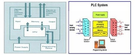
A basic Programmable Logic Controller system consists of the following components:
Input/Output Section: The input section or input module consists of devices such as sensors, switches, and many other real-world input sources. The input from the input source is connected to the PLC via the input connector rail. The output section or output module can be a motor or solenoid or a lamp or heater whose function is controlled by changing the input signal.
CPU or central processing unit: This is the brain of the PLC. It can be a hexagonal or octagonal microprocessor. It performs all processing associated with the input signal to control the output signal based on the control program.
Programmer: A platform for writing programs or controlling logic. It can be a handheld device, a laptop or the computer itself.
Power supply: Typically operates on a 24 V power supply to power input and output devices.
Memory: The memory is divided into two parts - data memory and program memory. Program information or control logic is stored in the program memory of the user memory or CPU fetch program instructions. The input and output signals as well as the timer and counter signals are stored in the input and output external image memories, respectively.
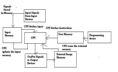
 The workflow of Programmable Logic Controller
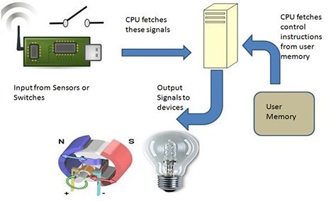
1. The input source converts the real-time analog electrical signals into appropriate digital electrical signals and applies them to the Programmable Logic Controller through the connector track.
2. These input signals are stored in locations in the external image memory of the Programmable Logic Controller called bits. This is done by the CPU to complete the control logic or program instructions written to the programming device by symbols or by mnemonics and stored in the user memory.
3. The CPU reads these instructions from the user memory and controls the output device by operating, calculating, and processing the input signals.
4. The execution result is then stored in the external image memory of the control output driver.
5. The CPU also checks the output signal and continuously updates the contents of the input image memory according to changes in the output memory.
6. The CPU also performs internal programming functions such as setting and resetting the timer to check the user memory.
If you want to learn more about Programmable Logic Controller, please contact us: sygckj@gmail.com.
Before we introduce the Programmable Logic Controller in detail, let us know why it is widely used.
First, they are user friendly and easy to operate.
Second, they eliminate the need for hardwired relay logic.
Third, suitable for industrial automation.
Fourth, its input and output modules can be extended as needed
A basic Programmable Logic Controller system consists of the following components:
Input/Output Section: The input section or input module consists of devices such as sensors, switches, and many other real-world input sources. The input from the input source is connected to the PLC via the input connector rail. The output section or output module can be a motor or solenoid or a lamp or heater whose function is controlled by changing the input signal.
CPU or central processing unit: This is the brain of the PLC. It can be a hexagonal or octagonal microprocessor. It performs all processing associated with the input signal to control the output signal based on the control program.
Programmer: A platform for writing programs or controlling logic. It can be a handheld device, a laptop or the computer itself.
Power supply: Typically operates on a 24 V power supply to power input and output devices.
Memory: The memory is divided into two parts - data memory and program memory. Program information or control logic is stored in the program memory of the user memory or CPU fetch program instructions. The input and output signals as well as the timer and counter signals are stored in the input and output external image memories, respectively.
1. The input source converts the real-time analog electrical signals into appropriate digital electrical signals and applies them to the Programmable Logic Controller through the connector track.
2. These input signals are stored in locations in the external image memory of the Programmable Logic Controller called bits. This is done by the CPU to complete the control logic or program instructions written to the programming device by symbols or by mnemonics and stored in the user memory.
3. The CPU reads these instructions from the user memory and controls the output device by operating, calculating, and processing the input signals.
4. The execution result is then stored in the external image memory of the control output driver.
5. The CPU also checks the output signal and continuously updates the contents of the input image memory according to changes in the output memory.
6. The CPU also performs internal programming functions such as setting and resetting the timer to check the user memory.
If you want to learn more about Programmable Logic Controller, please contact us: sygckj@gmail.com.


