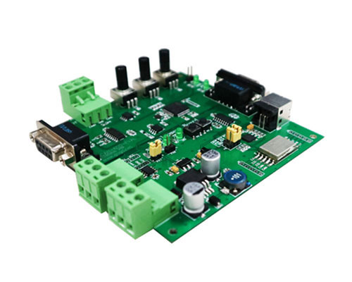
ECU data decoding module development board
- Brand:
- GCAN
- Model:
- GCAN-600-EVAL
- Application:
- Simulate the ISO 15765 protocol to send data More convenient and safe for automobile electronics development
-
1. Function Overview
GCAN-600 is OBD decoding development module. Users only need to integrate GCAN-600 into their own systems, then they can easily get the sensor status information inside the car. Choosing GCAN-600 will reduce user’s development time and cost.
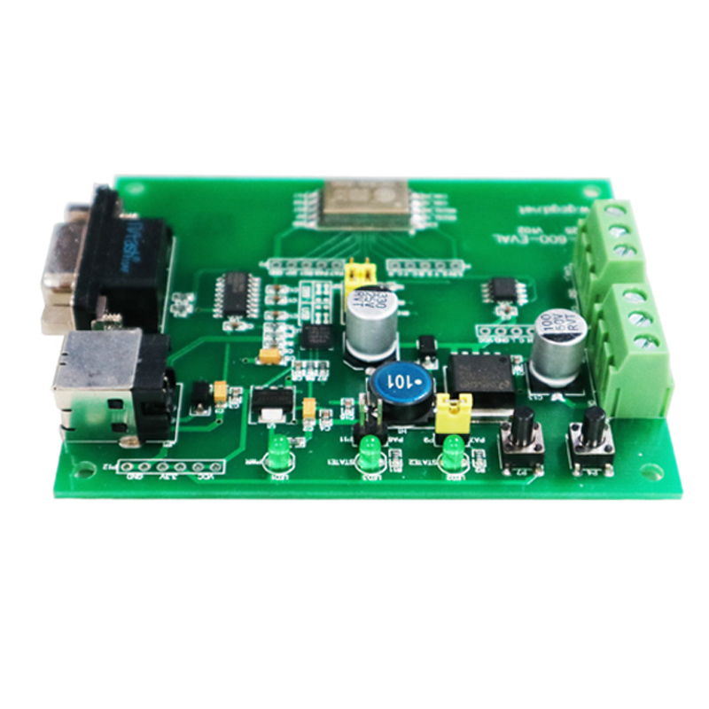
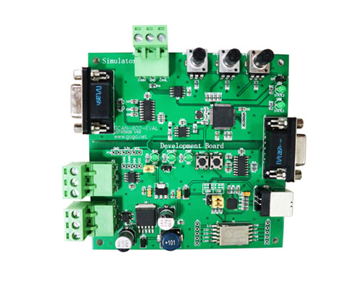
GCAN-600-EVAL V2/V3 are the dedicated development boards of GCAN-600 module. The development board has integrated one GCAN-600 module and all the required peripherals of GCAN-600 module. Users can directly use it in automobile and savings in development time and cost.
2. Properties at a Glance
a. GCAN-600-EVAL V2 development board
GCAN-600-EVAL V2 development board provides two communication methods, which are serial and USB. User can use a computer or MCU to send data to the module. GCAN-600-EVAL V2 development board supply two power supply mode of USB power supply and external power supply.

Details of the various parts are described below:
(1) Reset button: Used for module reset.
(2) Upgrade button: For the module upgrade.
(3) Run indicator: When his indicator flashes, the module is running normally.
(5) Power light: When this indicator is on, the module is powered normally.
(6) Test point: Two kinds of voltage interface: + 5V, +3.3 V, GND.
(7) USB interface: Use PC USB interface to connect with GCAN-600 module. USB
interface has integrated the chip of USB to serial port, users can use serial
debugging assistant to debug. USB interface has integrated power supply, no
external power supply is required when used USB.
(8) RS232 interface: Standard RS232 interface and level. It can connect with the
computer, MCU, Bluetooth module and other peripheral modules, which can use
for debugging, expansion module using.
(11) USB / serial switch jumper: Use jumper cap to select which interface (7) (8) is
used.
(12) CAN bus interface: CAN bus can be directly connected to this interface.
(13) External power supply: 9-30V external power supply .
b. GCAN-600-EVAL V3 development board
GCAN-600-EVAL V3 has increase a function of the automobile OBD simulator than V2.
With OBD simulator, you can simulate all the ISO15765 protocol data transmission. The three potentiometers can be configured to all the parameter that in ISO15765 such as "vehicle parameter adjustment" and then output through CAN bus.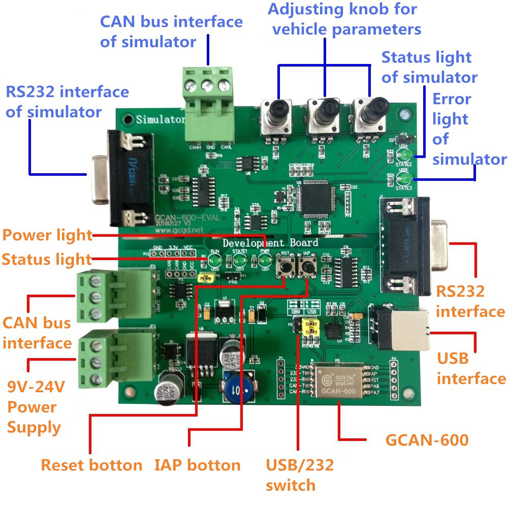
Typical OBD simulator's data include: speed, engine speed, voltage, water temperature, fuel position, engine load, the number of fault codes, acceleration pedal position, and so on. Users can use a RS232 cable to connect the RS232 port which is in the blue position, and configure the function of the three potentiometers through the serial port command. After completion, the user can output the ISO15765 protocol data through the "Simulator CAN bus interface.
The advantages of using OBD simulator are as follows:
① When user is developing or debugging the program, he doesn't need to be tested frequently in the automobile. Using the OBD simulator can shorten the development cycle.
② Use OBD simulator to replace the test on the automobile can effectively prevent the damage to the automobile caused by design defects.
③ All the simulator's data can be customized according to the customer.
3. Recommendation
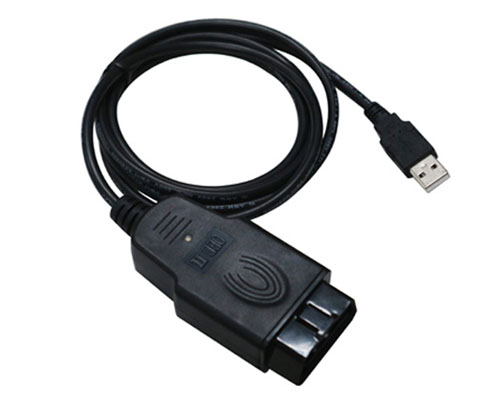
If the user wants to decode or monitor the raw data of the CAN bus , debugging the CAN bus equipment, you need to use USBCAN-OBD device.
USBCAN-OBD is the CAN bus analyzer specifically for automotive electronics development, diagnosis, analysis, and decode. Users can use the PC USB interface to connect to CAN bus network via the OBD interface, which can read the CAN bus data of the automobile, and analyze the specific significance of the data in ISO15765 directly.
Click on the picture to learn more
-
GCAN-600-EVAL V2 development board provides two communication methods, which are serial and USB. User can use a computer or MCU to send data to the module. GCAN-600-EVAL V2 development board supply two power supply mode of USB power supply and external power supply.

Details of the various parts are described below:
(1) Reset button: Used for module reset.
(2) Upgrade button: For the module upgrade.
(3) Run indicator: When his indicator flashes, the module is running normally.
(5) Power light: When this indicator is on, the module is powered normally.
(6) Test point: Two kinds of voltage interface: + 5V, +3.3 V, GND.
(7) USB interface: Use PC USB interface to connect with GCAN-600 module. USB
interface has integrated the chip of USB to serial port, users can use serial
debugging assistant to debug. USB interface has integrated power supply, no
external power supply is required when used USB.
(8) RS232 interface: Standard RS232 interface and level. It can connect with the
computer, MCU, Bluetooth module and other peripheral modules, which can use
for debugging, expansion module using.
(11) USB / serial switch jumper: Use jumper cap to select which interface (7) (8) is
used.
(12) CAN bus interface: CAN bus can be directly connected to this interface.
(13) External power supply: 9-30V external power supply . 
-
GCAN-600(CAN bus decoding) module
User Manual(Click to view)Please ask for more information to the Engineer.
E-mail:2881884588@qq.com Contact us
E-mail: GCANgckj@gmail.com
2881884588@qq.com
Mobile: +86 18309815706
Web: www1.gcanbox.com


