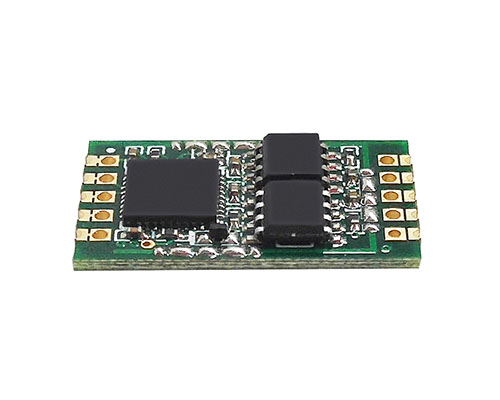
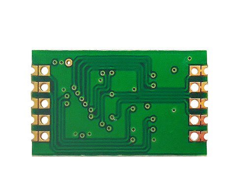
Embedded UART-CAN Module
- Brand:
- GCAN
- Model:
- GCAN-601
- Application:
- UART to CAN. Embedded system integration. Serial fieldbus transformation. IC
-
1.Overview
The GCAN-601 is a communication converter that integrates with one CAN-Bus interface, one UART interface. The GCAN-601 can be directly connected to the UART interface of MCU, which can make a CAN-Bus communication without changing its original hardware.
In normal operation, the GCAN-601 module is in a state of real-time monitoring of the CAN bus and the UART bus. Once a data is received on one bus, it is immediately parsed and loaded into its own buffer. According to the set working mode, the data on the bus is sent to the other bus to realize the conversion of the data format.
2.Properties at a glance
Standard UART level, can be directly connected with MCU
Support serial baud rate 600bps~921600bps
Supply three kinds of conversion modes: transparent conversion, transparent conversion with identity, format conversion
Configure three kinds of conversion directions: bidirectional conversion, CAN→ serial interface, serial interface→ CAN
CAN-Bus support CAN2.0A and CAN2.0B frame format, conform to ISO/DIS11898 specification
Support CAN-Bus communication baud rate: 5Kbps~1Mbps
Use 3.3V DC power supply
Save configured parameters in storage, call the latest parameters automatically after supplying power
Working temperature: -40.00℃~ + 85.00℃
Dimensions: 22mm(L) ×13mm(W)3. Introduction
3.1 Interface definition3.3 Typical application circuit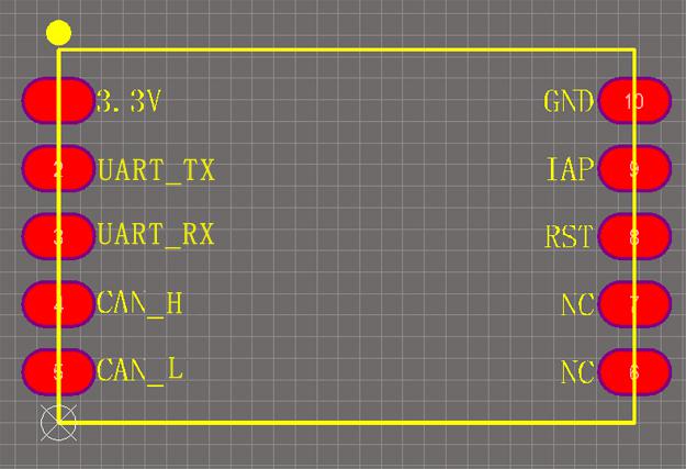
Pin Name Definition 1 3.3V Power +3.3V interface 2 UART_TX UART TX pin 3 UART_RX UART RX pin 4 CAN_H Connect CAN_H 5 CAN_L Connect CAN_L 6 GND GND interface 7 IAP Update kernel 8 RST Reset pin 9/10 NC No connection
3.2 Seal and package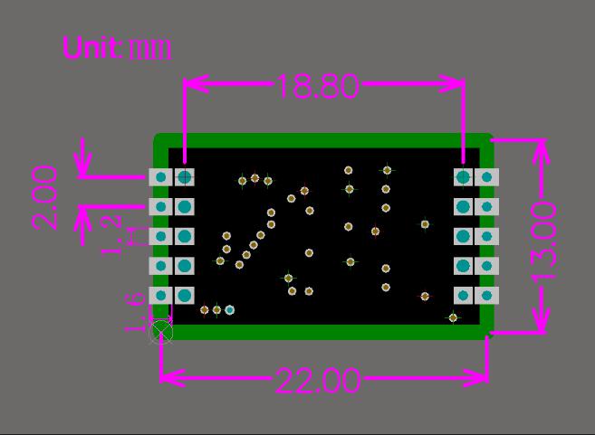
a. Power module
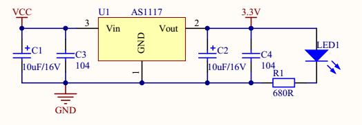
The power circuit mainly includes LM2576 power module and AMS1117 module. LM2576 power module uses for power supply, rated voltage 9-30V. The AS1117 module is mainly used for voltage conversion, and converts 5V to 3.3V to power the GCAN-601 module.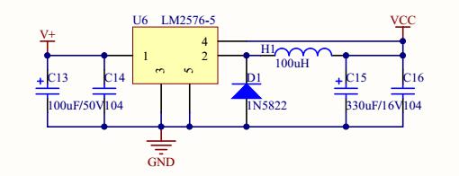
 b. Serial communicationSerial communication mainly adopts RS232 transceiver SP232EEN.
Note : the TXIN of the RS232 transceiver chip needs to be connected to the TX interface of the GCAN-601 module, RXOUT is connected to the RX interface of the GCAN-601 module, and the VCC is 5V.3.4 Working mode
Mode Function Normal mode General mode of module leaving the factory Configuration mode In normal mode, connect the IAP pin to 3.3V and the module will enter the configuration mode. (RET button / re-powered to return to normal mode.) Upgrade kernel Connect the IAP pin to 3.3V, and then power up to enter IAP mode. The kernel can be upgraded through the UART. (This mode should be used under the guidance of our engineer.)
4. Application sample
4.1 Transparent conversion
4.1.1 Frame format
Serial frame: data flow or data with protocol, communication format: 1 start, 8 data, 1 stop
CAN-Bus frame: keep the CAN message format
4.1.2 Conversion mode
1. Serial frame convert CAN message
All of serial frame data convert into data area of CAN message. Frame ID is configured by user, as shown figure 4.1.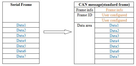
2. CAN message convert serial frame
Check “Permit frame information transmits to serial frame” and “Permit frame ID transmits to serial frame”, as shown figure 4.2.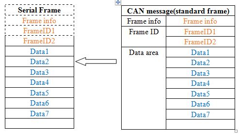
Figure 4.2 CAN message convert serial frame (transparent conversion)
4.2 Transparent conversion with identity
Details see the "3.3.2 Transparent conversion with identity".
4.2.1 Frame format
1. Serial frame
Details see the "3.3.2 Transparent conversion with identity".
Figure 4.3 time format of serial frame (transparent conversion with identity)
2. CAN-Bus frame
Keep CAN message format, just convert corresponding to frame ID of CAN into the serial frame.
4.2.2 Conversion mode
1. Serial frame convert CAN message
The initial position ranges from 1~7, length ranges from 1~2 (standard frame) or 1~4 (extend frame).
Suggested values:
For standard frame: initial position 1, standard frame 2.
For extend frame: initial position 1, extend frame 4.
For example of standard frame: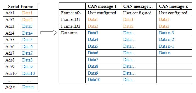
Figure 4.4 serial frame convert CAN message (transparent conversion with identity)
2. CAN message convert serial frame
For example of standard frame: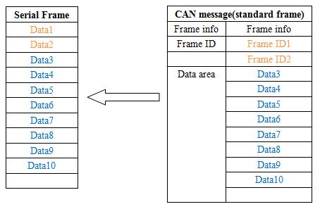
Figure4.5 CAN message convert serial frame (transparent conversion with identity)
4.3 Format conversion
The GCAN-601 module has data conversion format, as shown the picture.
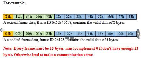
Every CAN frame contains 13 bytes, and 13 bytes contains CAN frame + frame ID + frame data.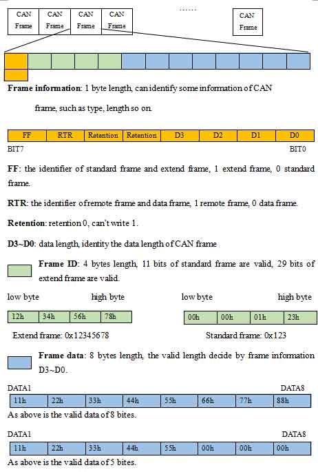
- Standard UART level, can be directly connected with MCU
Support serial baud rate 600bps~921600bps
Supply three kinds of conversion modes: transparent conversion, transparent conversion with identity, format conversion
Configure three kinds of conversion directions: bidirectional conversion, CAN→ serial interface, serial interface→ CAN
CAN-Bus support CAN2.0A and CAN2.0B frame format, conform to ISO/DIS11898 specification
Support CAN-Bus communication baud rate: 5Kbps~1Mbps
Use 3.3V DC power supply
Save configured parameters in storage, call the latest parameters automatically after supplying power
Working temperature: -40.00℃~ + 85.00℃
Dimensions: 22mm(L) ×13mm(W)
Connection mode Serial port PCB pad/2.08 raw pin CAN port PCB pad/2.08 raw pin Interface feature Serial interface UART Serial port baud rate 600bps~921600bps CAN interface ISO 11898 standard, CAN2.0A/B CAN baud rate 1000K、500K、250K、200K、125K、100K、50K、20K、10K、5K CAN terminal resistant Hasn't integrated, you can add it between CAN_H and CAN_L in your need Power supply Voltage +3.3V DC Current 100mA(MAX) Environmental test Working temperature -40℃~+85℃ Working humidness 15%~90%RH, without condensation Basic information Dimension 22mm *13mm Weight 10g
E-mail: sygckj@gmail.com
2881884580@qq.com
Mobile: +86 17742765166


