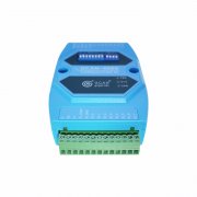
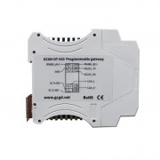
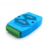
Modbus master collects J1939 protocol data through GCAN-204/
Want to buy GCAN-204 Modbus J1939(CAN) converter. Please clieck: https://www.alibaba.com/product-detail/GCAN-204-RS485-serial-CAN-bus_60734067418.html
Problems:
1. Use the Modbus master station to read the speed information of the vehicle engine(J1939).
2. How to use the Modbus master station to read the parameters of CANopen electronic ruler and other equipment
3. How to use the Modbus master station to control the servo motor driver
Principle:
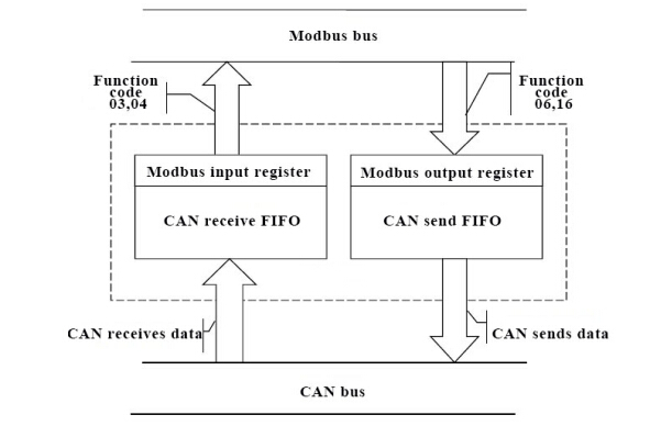
GCAN-204 is a Modbus RTU slave to CAN device, which can bind the ID of CAN bus data with the address of Modbus register. After the CAN terminal of GCAN-204 receives the data, the device can send CAN data. Stored in the corresponding register, waiting for the Modbus master to read, the value written by the Modbus master to the GCAN-204 register can also be converted to the CAN data of the corresponding ID and sent to the CAN terminal. This completes the communication between the CAN bus and the Modbus bus. Schematic diagram 1 is shown.
Solution:
We use the computer as the Modbus master to read and write the Modbus slave. First of all, it is necessary to configure the working parameters of GCAN-204. The following focuses on how to configure the mapping table of CAN data ID and register first address to realize the mutual conversion of CAN data and Modbus bus data. Perfect solution for Modbus J1939 coversion
1, GCAN-204 configuration
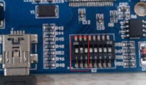
1.1 Disconnect the GCAN-204 Modbus J1939 module and turn it off. Turn the DIP switch 2 to on as shown, then power on the module.
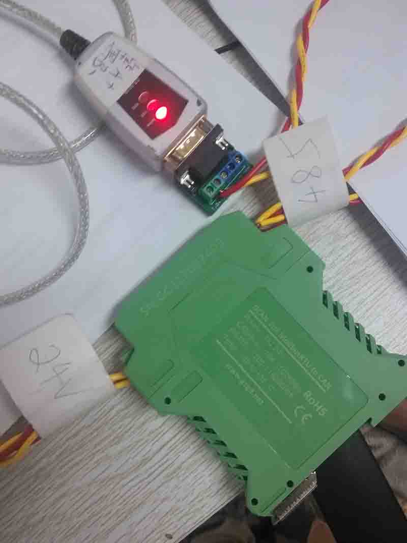
1.2 Then connect the device with RS485 to CAN line, as shown.
1.3 Enter the GCAN-204 Modbus J1939 bridge configuration software
 1.4 Select the correct com port and click “Connect”
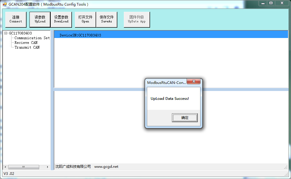
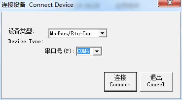 1.5 Click “Read Parameters” to display “UPload Date Success” and click OK.
 1.6 Enter “Recieve CAN” to enter the receiving CAN bus data mapping table, click “Add” button to add a blank data.
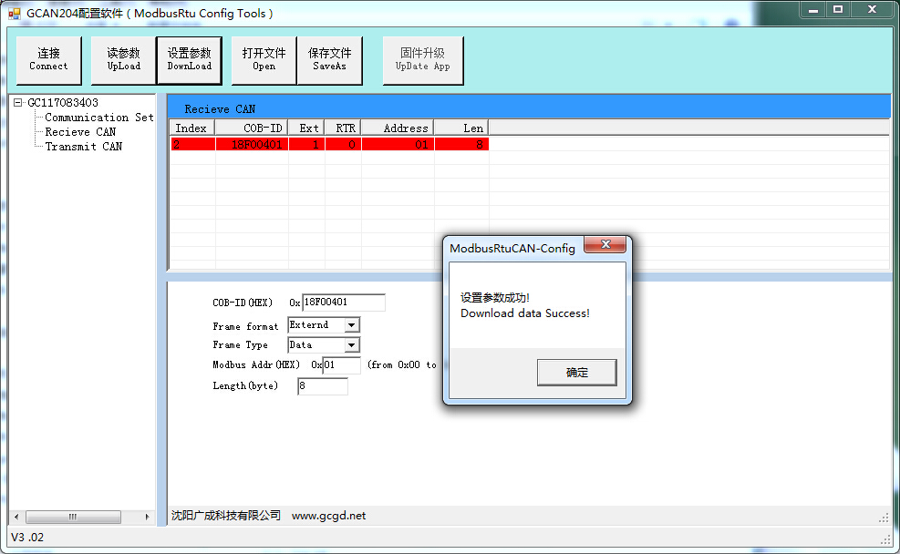
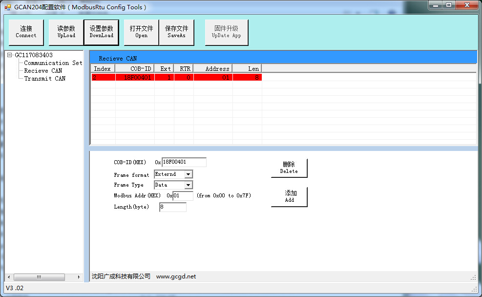 After 1.7, the newly added data is modified. The settings in this experience are: COB-ID 18F00401, extended frame, data frame, modbus register first address 01, data length 8. Once set, click the "Set Parameters" button
Email/Skype: seven.gcan@gmail.com
Tel: +86 17742765166


After the GCAN-204 Modbus CAN gateway is successfully set, the device dial switch 2 is dialed down. After the power is turned on again, the settings take effect.
At this point, the device can connect to the CAN device and the Modbus master station for communication. Note: The mapping relationship can be configured as needed.
Or contact us:
2. GCAN-204 Modbus J1939 equipment and diesel engine ECU connection
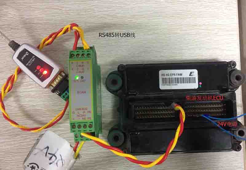
Connect GCAN-204 and J1939 port of diesel engine ECU with twisted pair cable, connect GCAN-204 to computer with RS485 to USB cable, and power GCAN-204 and diesel engine ECU with 24V.
3, Modbus poll software receives data
Use the Modbus poll software as the master station to read the data, open the Modbus poll software, click on the Connection connection, select the baud rate as 57600, then click OK. Then select the 03 function code, the first address read is 01, we can see that the data is constantly changing. Prove that the Modbus master has successfully collected the speed data sent by the CAN device. The data forwarding from the CAN end to the Modbus end is realized. As shown in Figure 10.
This experience is to realize the communication between CAN bus and Modbus bus. It can be applied to PLC to use GCAN-204 to collect the speed data of Cummins engine, read the parameters of CANopen electronic ruler and other equipment, control servo motor driver and so on.
The GCAN-204 device solves the problem that the CAN bus and the Modbus bus cannot communicate directly, which greatly facilitates the communication between engineers on different buses and shortens the development cycle.
Email/Skype: seven.gcan@gmail.com
Tel: +86 17742765166


