GCAN-4055 working status
GCAN-4055 is connected with CAN bus:
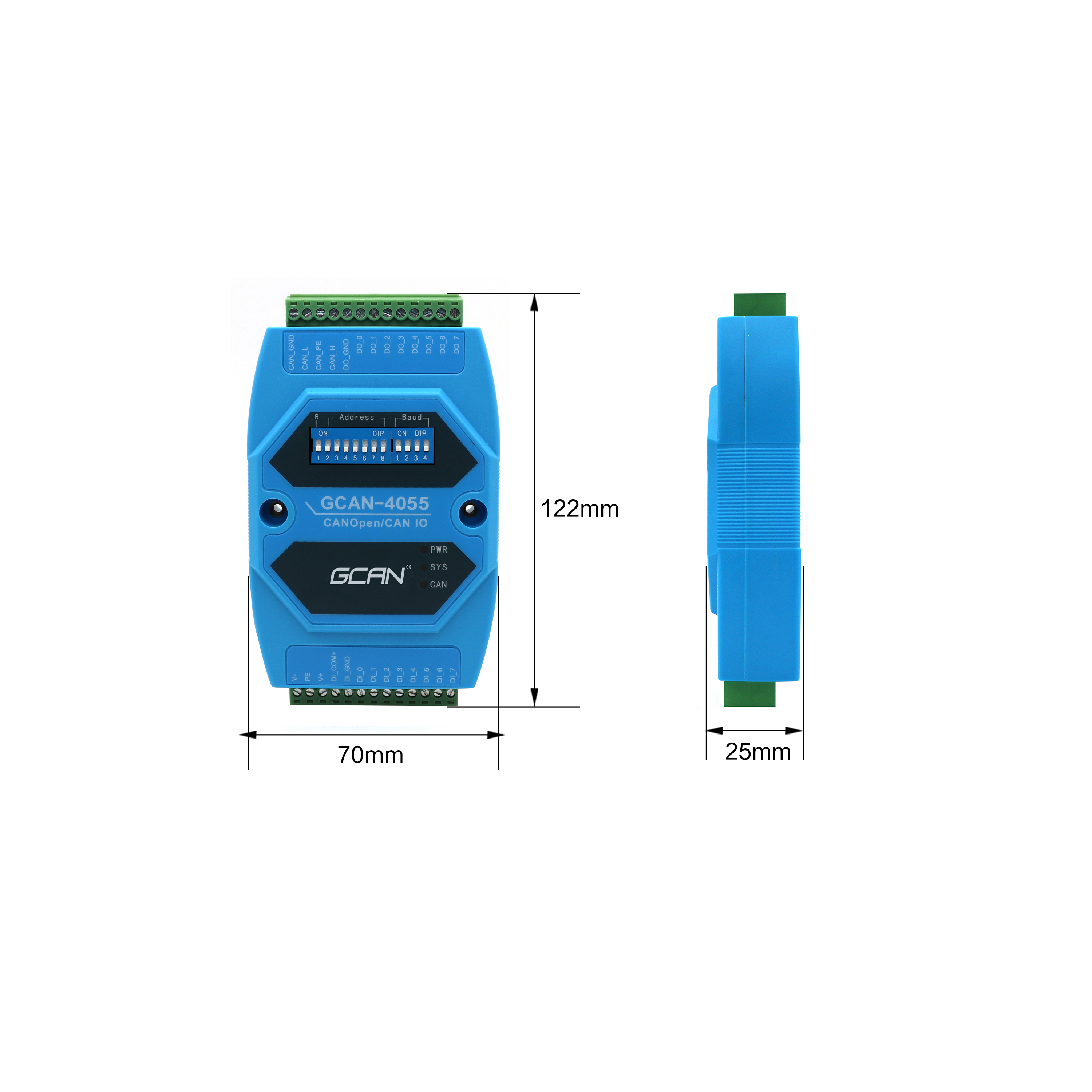
The GCAN-4055 module integrates one CAN bus channel, which is derived from pluggable terminal blocks. It can be used to connect a CAN bus network or a CAN bus interface device. Definition of terminal blocks.
In actual use, in most cases, it is only necessary to connect CAN_H with the bus CAN_H, and connect CAN_L with the bus CAN_L to achieve communication.
CANopen IO module-GCAN-4055 module interface definition: GCAN-4055 uses terminal wiring. The GCAN-4055 module's DIP switch is the closest to the reset button. The default is the top. It is the debugging interface. Please do not dial. The 7-bit right of the reset button is the baud rate setting switch. The rightmost 4 bits are the baud rate setting switches. The left side is the high position and the right side is the low position of the  module terminal pin function descriptions as follows: V +: Connect to the positive pole of the power supply (+ 10V ~ + 30V DC) V-: Connect to the power socket PE: Shielded wire interface CAN_L: CAN bus low Line (Low) CAN_H: CAN bus high line (High) CAN_PE: CAN bus shield CAN_GND: CAN bus ground (GND) DI_COM: Reference ground for dry contact input signal DI_GND: Connect to wet contact input common ground DI_0 ~ DI7: Connect digital input channel 0 ~ 7 positive terminal DO_GND: Ground reference for digital output signal DO_0 ~ DO7: Connect digital output channel 0 ~ 7 positive terminal
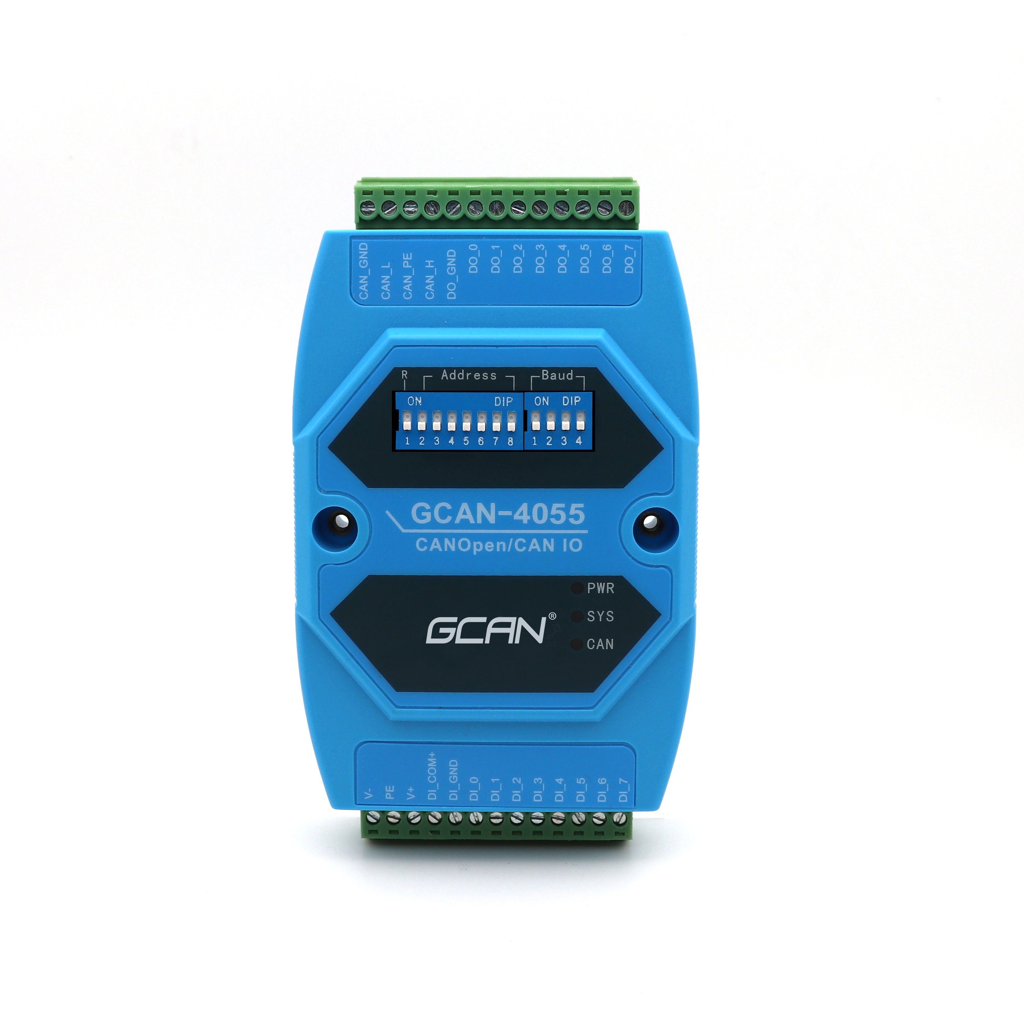
CANopen IO module——GCAN-4055 power connection: GCAN-4055 module supports + 9-30V DC power supply commonly used in industrial field. In order to ensure the reliable operation of the module, it is recommended that you use a + 12V or + 24V DC DC stabilized power supply. GCAN -4055 module power supply provides reverse connection protection to prevent users from damaging the module due to incorrect power wiring. CANopen IO module——GCAN-4055 is connected to CAN bus: The connection method of GCAN-4055 module to CAN bus is introduced in 2.2. Connect CAN_H to CAN-bus network using a linear topology. The two terminals of the bus farthest need to install 120Ω Termination resistance; if the length is greater than 2, a 120Ω termination resistance is installed in the middle. For branch connections, the length exceeds 3 meters.
CANopen IO module——GCAN-4055 and CAN bus terminal resistance: In order to enhance the reliability of CAN communication and eliminate the CAN bus terminal signal reflection interference, the two farthest ends of the CAN bus network usually need to add a terminal matching resistance. For example, the characteristic impedance of the twisted pair is 120Ω, so the two terminals on the bus should also integrate 120Ω termination resistors. If other converters on the network use different transceivers, the termination resistance should be calculated separately
GCAN-4055 module does not integrate 120Ω termination resistor. If the length is greater than 2, you do not need to install a 120Ω termination resistor in the middle. When you need to use it, you can connect the resistors to CAN_H and CAN_L to open the CANopen IO module-GCAN-4055 system status indicator: GCAN-4055 module has a PWR indicator, a COM indicator, and a CAN indicator to indicate The operating status of the device. The specific indication functions and status of these 3 indicators
1 After the GCAN-4055 module is powered on, the PWR, COM, and CAN indicator lights immediately; 2. When the GCAN-4055 module completes the self-test, the CAN light goes out and the SYS light flashes; 3. When there is data transmission on the CAN side , CAN light flashes and goes out when there is no data; 4. If there is a communication error on the CAN bus, the CAN light will turn red
