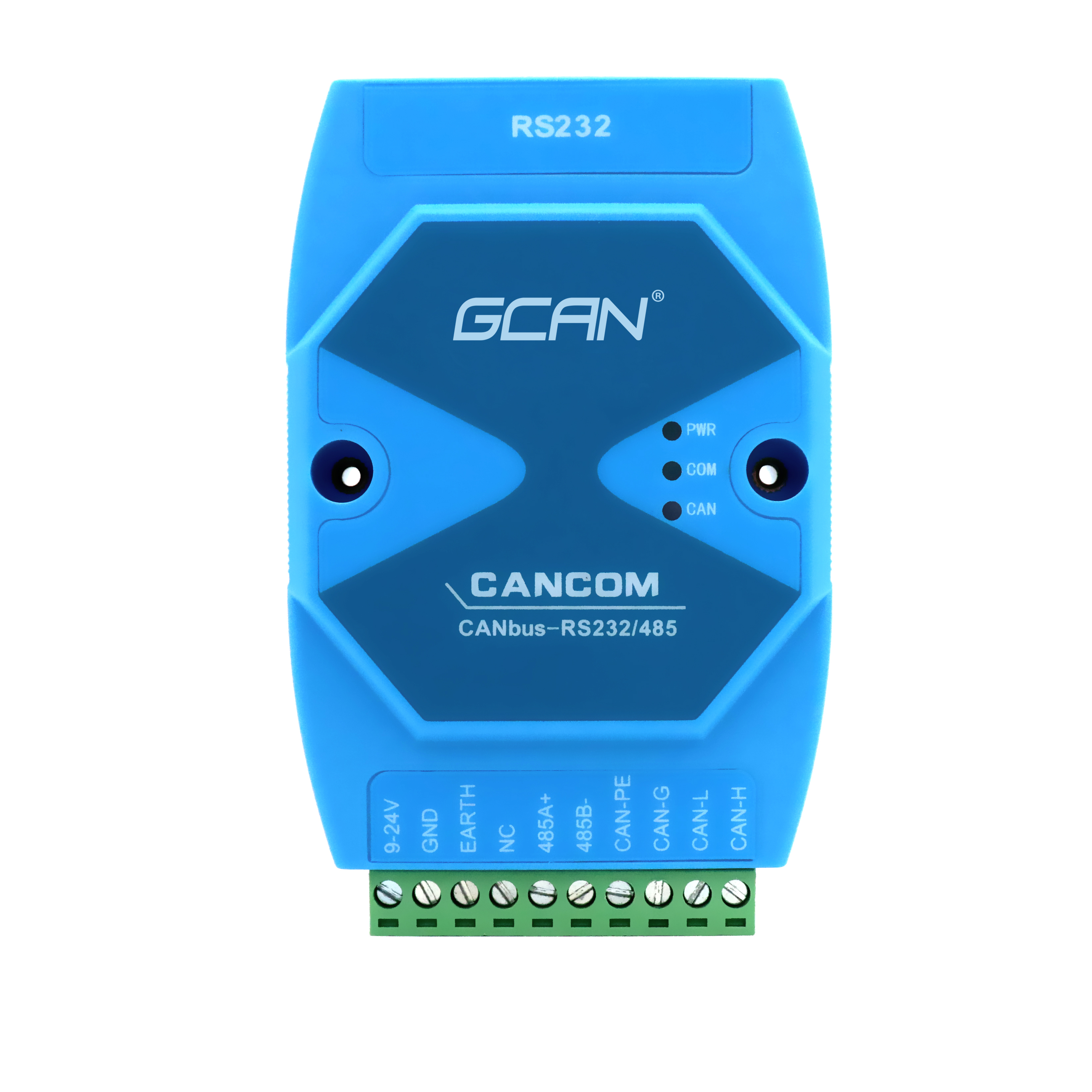
GCAN-207 configuration parameter conversion
Configuration conversion parameters: CANCOM module supports 3 working modes: transparent conversion, transparent tape identification conversion, format conversion. Support 3 kinds of conversion directions: bidirectional conversion, CAN only to serial port, only serial port to CAN. The operating mode and direction of conversion can be selected in the "Conversion Parameters" tab. The three conversion modes are detailed below.
Transparent conversion: The meaning of transparent conversion is that the converter only converts the bus data of one format as it is to the data format of another bus without attaching data and modifying the data. This achieves the exchange of data formats without changing the data content, and the converter is as transparent as the bus at both ends. In this way, the user communication load is not increased, and the data can be converted as it is in real time, and the data of a large flow can be transmitted. In this mode of operation, in addition to setting the baud rate of the two buses, the user also needs to select whether to allow CAN frame ID or frame information to be sent to the serial frame in the "Conversion Parameters" tab. "Allow CAN frame information to be forwarded to serial frame" is only used in "transparent conversion" mode. If checked, the converter will work to add the frame information of the CAN message to the first byte of the serial frame. The frame information of the CAN is not converted when it is not selected. "Allow CAN frame ID to be forwarded to serial frame" is only used in "transparent conversion" mode. If checked, the converter will work to add the frame ID of the CAN message before the frame data of the serial frame. After that (if frame information conversion is allowed). The frame ID of the CAN is not converted when it is not selected. If "Allow CAN frame identification to be forwarded to serial frame" is checked, the transmission identifier can be set in the "CAN Parameter" tab. This transmission identifier is the frame ID when the serial bus is sent to the CAN bus.


Transparent tape logo conversion: Transparent tape logo conversion is a special use of transparent conversion, and no protocol is attached. This conversion method is based on the common characteristics of the usual serial frame and CAN message, so that the two different bus types can easily form the same communication network. This method can convert the "address" in the serial frame to the identification field of the CAN message, where the serial frame
The "address" can be configured in both the start position and the length of the serial frame, so in this way, the converter can be adapted to the user's custom protocol to the maximum extent. In this mode of operation, in addition to setting the baud rate of the two buses, the user also needs to set the "position of the CAN frame identifier in the serial frame". This parameter is only used in the "Transparent Tape Identification Conversion" mode. When the serial port data is converted into a CAN message, the offset address of the frame byte of the CAN message in the serial frame and the length of the frame ID can be selected. The "start offset" is from the first few bytes of the serial frame, and the "length" is the length, in bytes, of the frame ID sent to the CAN bus. The starting address ranges from 1 to 7, and the length ranges from 1 to 2 (standard frame) or 1 to 4 (extended frame). The "interval between serial frames" is only used in the "transparent zone identification conversion" mode. The minimum time interval between two serial frames when the user sends a serial frame to the converter, which is in units of "time to transmit a single character." The range is 1 to 20 characters. Format conversion: Format conversion is one of the simplest usage patterns. The data format convention is 13 bytes and contains all the information of the C frame. In the format conversion mode, the original CAN data frame can be sent and received through the serial port. The format conversion uses a common data definition, which is very convenient for users to carry out secondary development. The data format in the format conversion mode. The configuration of the transmission direction conversion direction is divided into three types: bidirectional conversion, CAN only serial port, and serial port only CAN. By switching the setting of the direction, it is possible to eliminate data interference on the bus side that does not require conversion. Bidirectional: The converter converts the serial bus data to the CAN bus and also converts the CAN bus to the serial bus. Serial port only → CAN: Only the data of the serial bus is converted to the CAN bus, and the total CAN data is not converted to the serial bus. CAN-only serial port: Converts only the CAN bus data to the serial line without converting the serial bus data to the CAN bus.
<img alt="RS232 / 485 to can conversion gateway" "="" data-cke-saved-src="/uploads/allimg/191113/1-19111316132M58.jpg" src="/uploads/allimg/191113/1-19111316132M58.jpg" style="width: 1000px; height: 1000px;" title="RS232 / 485 to can conversion gateway">
<img alt="RS232 / 485 to can conversion gateway" "="" data-cke-saved-src="/uploads/allimg/191113/1-19111316132M58.jpg" src="/uploads/allimg/191113/1-19111316132M58.jpg" style="width: 1000px; height: 1000px;" title="RS232 / 485 to can conversion gateway">


