How to install and use GCAN-206
Driver and software installation
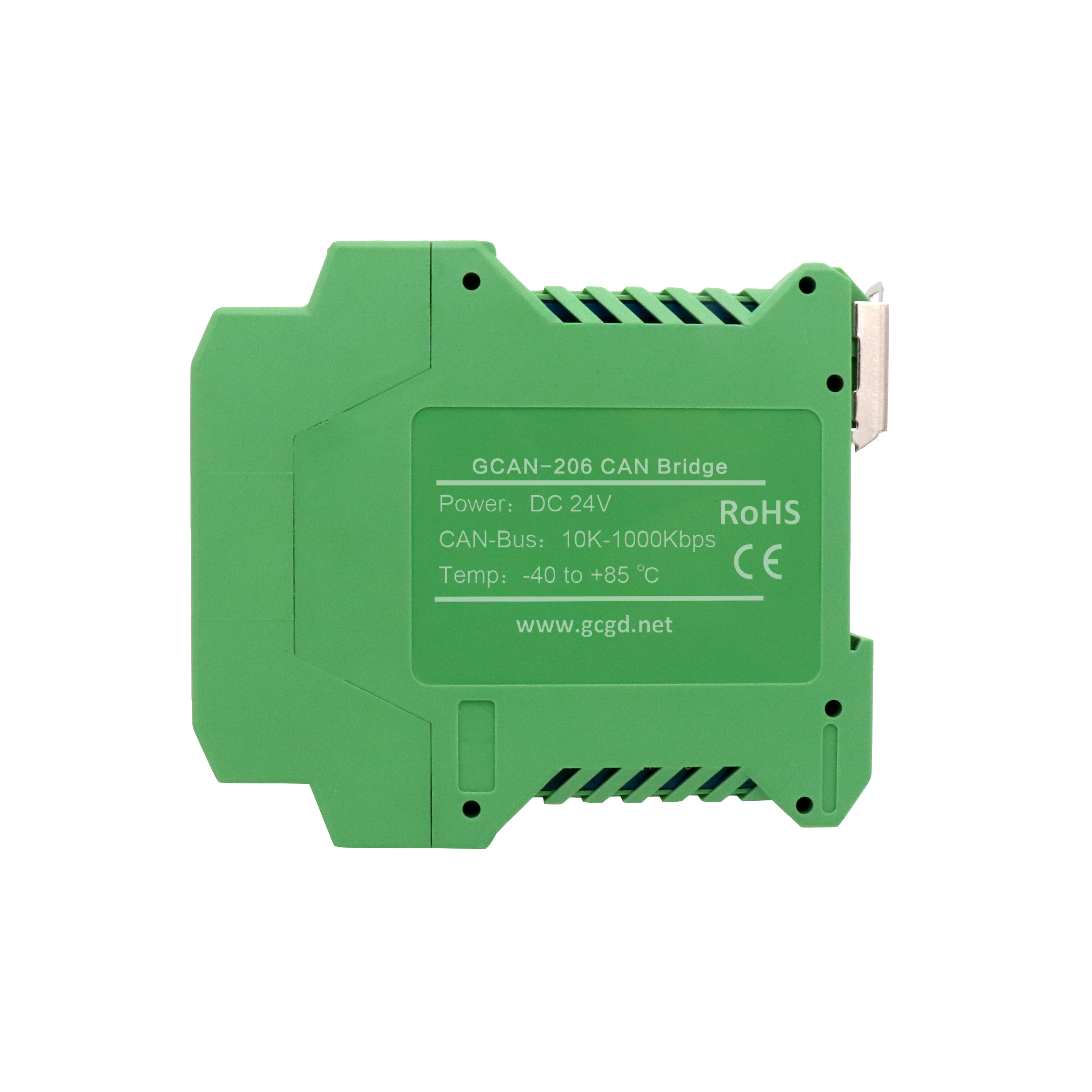
Before the driver and software installation, please ensure that the account you are logged into Windows is the administrator, or the user account has the relevant permissions to install the driver and software, otherwise the installation may fail. How to confirm the Windows account permissions: Control Panel - User Account Users can complete the installation and installation of the driver and software by directly installing the ECANTools software. To install the driver manually, go to the “Driver driver” folder on the CD and select the installation file (DriverSetup.exe/DriverSetup64.exe) corresponding to the system (32/64 bit) for manual installation. Driver and software uninstallation users can uninstall the installed device driver by running the above DriverSetup.exe/DriverSetup64.exe and clicking the "Uninstall" button. The ECANTools software can be uninstalled by the user via Add/Remove Programs. The GCAN-206 module interface card is connected to the PC and has a plug-and-play feature, so the user can directly supply power to the GCAN-206 module interface card using the PC's USB interface. USB bus power mode USB bus power mode is suitable for monitoring CANBUS data status. External power supply mode Use external power supply (DC+24V) to connect to the DC24V power socket of GCAN-206 module interface card. At this time, the indicators DAT and SYS are lit; Then connect the PC to the GCAN-206 module interface card through the Mini-USB cable, and the GCAN-206 module interface card will work normally. The module mounting GCAN-206 module is installed as shown below. A flat-blade screwdriver can be used to assist in mounting the module to the DIN rail. The GCAN-206 module ground is connected to the rail of the mounting module. If the rail is attached to a grounded metal component board, the module is automatically grounded and does not require an external ground wire. If the rail is attached to an ungrounded base, the rail must be attached to the nearest ground terminal. After the module is installed, it can be put into operation after being powered on. Connected to the CAN bus The GCAN-206 module integrates two CAN channels, which are led out by a 4Pin terminal block and can be used to connect two CAN-bus networks or CAN-bus interfaces. In actual use, in most cases, only CAN_H needs to be connected to bus CAN_H, CAN_L can be connected to bus CAN_L to realize communication USB connection. The USB interface of GCAN-206 module interface card conforms to USB2.0 full speed protocol specification, and can have USB1.1. Standard, USB2.0 standard, USB3.0 standard PC connection communication. The GCAN-206 module interface card is connected to the PC as follows: Use a screwdriver to tilt the green casing, remove the casing body, connect directly to the PC's USB interface via the Mini-USB cable, and provide the GCAN-206 module interface card from the PC's USB interface. +5V power supply. After the driver and software are installed normally, insert the device into the USB interface of the PC, and the new USBCAN device can be found in the PC Device Manager. The driver name is “GC-Tech USBCAN Device”. If there is no yellow exclamation mark or question mark, the device driver is normal. , The USBCAN device is properly connected to the PC. CAN connection GCAN-206 module access CAN bus connection mode: Connect CAN_H to CAN_H, CAN_L to CAN_L to establish communication. The CAN-bus network adopts a linear topology. The two terminals farthest to the bus need to be equipped with a 120Ω termination resistor. If the number of nodes is greater than 2, the intermediate node does not need to be equipped with a 120Ω termination resistor. For branch connections, the length should not exceed 3 meters CAN bus terminating resistors In order to enhance the reliability of CAN communication, eliminate the CAN bus terminal signal reflection interference, the farthest two endpoints of the CAN bus network usually need to add terminal matching resistors, as shown below Show. The value of the termination matching resistor is determined by the characteristic impedance of the transmission cable. For example, if the characteristic impedance of the twisted pair is 120Ω, then the two terminals on the bus should also be integrated with a 120Ω termination resistor. The GCAN-206 module interface card uses the 82C251 transceiver. If other nodes on the network use different transceivers, the terminating resistor must be calculated separately.
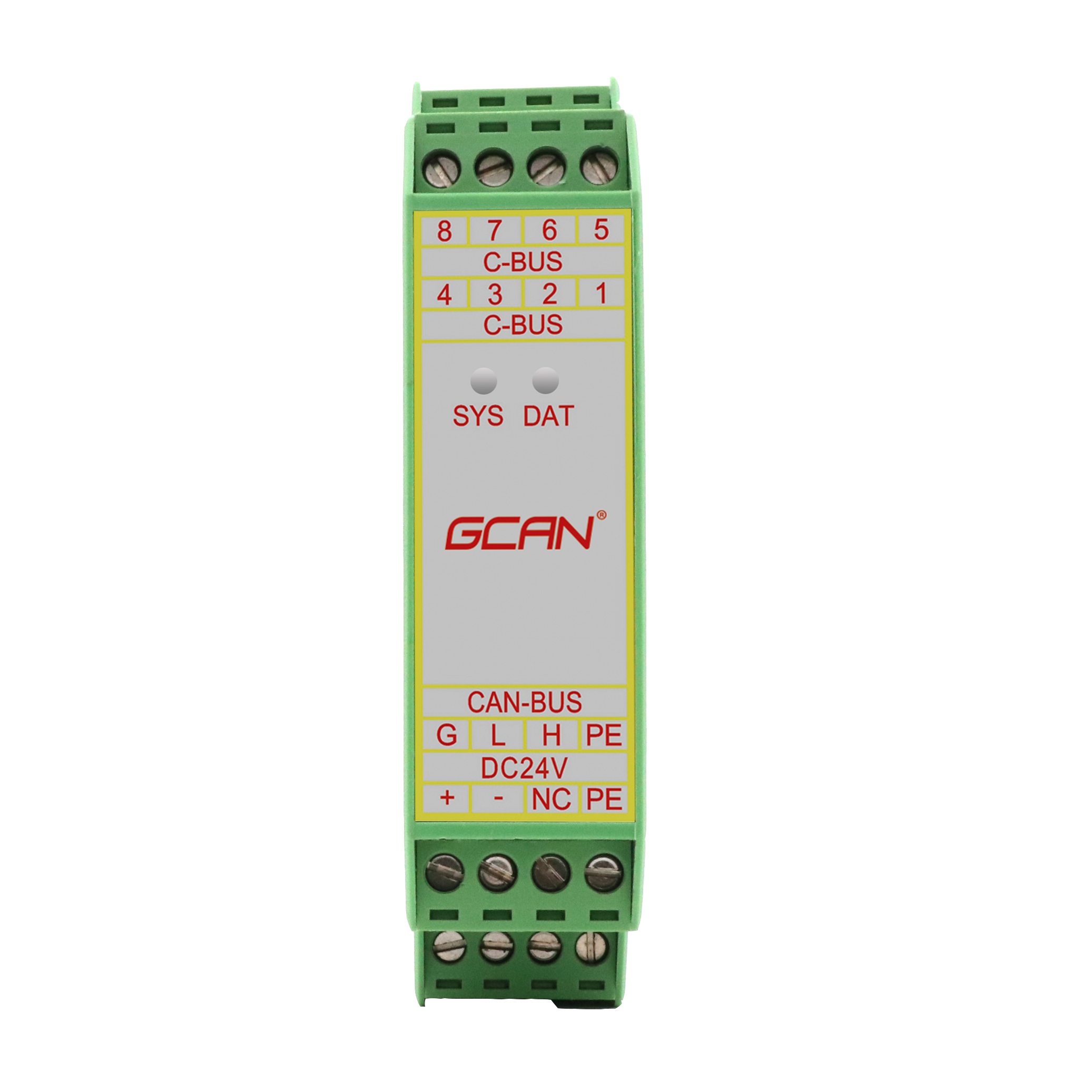
The GCAN-206 module does not have a 120Ω termination resistor integrated inside, and a resistor terminal is provided outside the module. When accessing the terminating resistor, connect the two ends of the resistor to CAN_L and CAN_H respectively. System status indicator GCAN-206 module has a SYS indicator to indicate the operating status of the device, and a DAT indicator to indicate data transmission. The specific indication functions of these two indicators are shown in the table below. When the two indicators are in various states, the status of the CAN bus is shown in the table below. After the GCAN-206 module is powered on, the system initialization status indicator SYS lights up, indicating that the device is powered and the system is initializing; otherwise, it indicates that the system has a power system failure. After the CAN1 end and the CAN2 end are connected normally, the data signal indicator DAT will flash when there is data between the buses.