
When USBCAN Analyzer don't receive data I
With more and more can bus applications, USBCAN analyzers are used more and more frequently. When you use USBCAN to debug the can bus, a situation where the data is not received you may encounter. This paper presents some experiences and methods of debugging can bus using GCAN Tech USBCAN Analyzer. Typically, it is because of wiring problems, mismatch of communication baud rates, mismatch of can bus resistance values, can bus target devices, or USBCAN analyzer problems. Today we are going to show the first 2 problems.
Preparation:
Windows system computer (desktop/ notebook)
GCAN USBCAN-II Pro Analyzer
Target CAN bus device(vehicle, Servo motor controller, ARM development board, etc)
1. Wiring problems
When wiring, the CANL of the USBCAN-II Pro analyzer needs to be connected to the CANL of the target CAN device, and the CANH of the USBCAN-II Pro analyzer is connected to the CANH of the target CAN device. At present, the most common wiring methods are Phoenix terminal, DB9 and OBD.
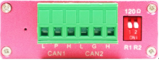
The following points should be paid attention when wiring the Phoenix terminal:
(1) When wiring, note that the CAN1 and CAN2 channels should correspond to the PC software;
(2) H and L should not be reversed (the position of the CAN device defined by different manufacturers is different, please follow the identification wiring);
(3) Tighten the terminal screws clockwise;
(4) Usually only need to connect L and H when wiring, P is shielded line, if there is strong magnetic interference, P can be connected to the earth;
(5) Twisted pair cable is recommended. If there is no strong electromagnetic interference, ordinary wires or DuPont lines can use for short-distance communication in a laboratory environment.
Wiring of DB9 connector: The internationally accepted definition is that the 2 pin is CAN low (CANL) and the 7 pin is CAN high (CANH). If a DB9 connector contains two CANs, you need to consult the device related manual.
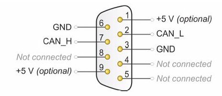
Figure 2 DB9 connector high speed CAN definition
Wiring of OBD connector: In most vehicle models, 6-pin is CAN high and 14-pin is CAN low, and some models, 3-pin is CAN high and 11-pin is CAN low. Please consult the relevant manual or use a multimeter to measure the voltage value of the tested pin to ground before wiring to confirm whether the tested pin is a CAN signal. Usually the silence voltage of the CAN signal is 2.5V. If the voltage is higher than 4V or less than 1V, it can be determined that it is not a high speed CAN signal. In this case, you need to check the manual to confirm whether it is fault-tolerant CAN, single-wire CAN, K-line or LIN line.
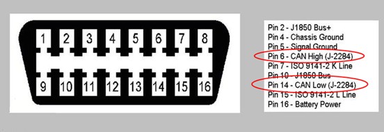
Figure 3 OBD connector high speed CAN definition
2. Terminating resistor
CAN bus require that there should each have a 120 Ω resistor in the farthest terminals of CAN bus to counteract the reflection of the electrical signal. There's a DIP switch on the side of the USBCAN-II Pro analyzer, which is convenient for the user to select whether to access the terminating resistor. In the experiment, it was found that in most cases, a 120 Ω resistor on the bus can achieve CAN bus communication of about 1 meter. However, it should be noted here that the resistance between L and H on the CAN bus is stable at around 64 Ω, that is, a 120 Ω resistor is required on each of the two terminals. If there are 5 CAN bus devices on the line, the three devices in the middle position cannot access the 120 Ω resistor.
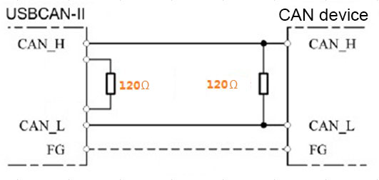
Figure 4 CAN bus terminating resistor
Other problems will be shown on next news, please stay tuned.
Welcome to contact us, if you want to know more about GCAN and GCAN products.
Tel: +86 13609896275.
Email: sygckj@gmail.com
Preparation:
Windows system computer (desktop/ notebook)
GCAN USBCAN-II Pro Analyzer
Target CAN bus device(vehicle, Servo motor controller, ARM development board, etc)
1. Wiring problems
When wiring, the CANL of the USBCAN-II Pro analyzer needs to be connected to the CANL of the target CAN device, and the CANH of the USBCAN-II Pro analyzer is connected to the CANH of the target CAN device. At present, the most common wiring methods are Phoenix terminal, DB9 and OBD.
The following points should be paid attention when wiring the Phoenix terminal:
(1) When wiring, note that the CAN1 and CAN2 channels should correspond to the PC software;
(2) H and L should not be reversed (the position of the CAN device defined by different manufacturers is different, please follow the identification wiring);
(3) Tighten the terminal screws clockwise;
(4) Usually only need to connect L and H when wiring, P is shielded line, if there is strong magnetic interference, P can be connected to the earth;
(5) Twisted pair cable is recommended. If there is no strong electromagnetic interference, ordinary wires or DuPont lines can use for short-distance communication in a laboratory environment.
Wiring of DB9 connector: The internationally accepted definition is that the 2 pin is CAN low (CANL) and the 7 pin is CAN high (CANH). If a DB9 connector contains two CANs, you need to consult the device related manual.
Figure 2 DB9 connector high speed CAN definition
Wiring of OBD connector: In most vehicle models, 6-pin is CAN high and 14-pin is CAN low, and some models, 3-pin is CAN high and 11-pin is CAN low. Please consult the relevant manual or use a multimeter to measure the voltage value of the tested pin to ground before wiring to confirm whether the tested pin is a CAN signal. Usually the silence voltage of the CAN signal is 2.5V. If the voltage is higher than 4V or less than 1V, it can be determined that it is not a high speed CAN signal. In this case, you need to check the manual to confirm whether it is fault-tolerant CAN, single-wire CAN, K-line or LIN line.
Figure 3 OBD connector high speed CAN definition
2. Terminating resistor
CAN bus require that there should each have a 120 Ω resistor in the farthest terminals of CAN bus to counteract the reflection of the electrical signal. There's a DIP switch on the side of the USBCAN-II Pro analyzer, which is convenient for the user to select whether to access the terminating resistor. In the experiment, it was found that in most cases, a 120 Ω resistor on the bus can achieve CAN bus communication of about 1 meter. However, it should be noted here that the resistance between L and H on the CAN bus is stable at around 64 Ω, that is, a 120 Ω resistor is required on each of the two terminals. If there are 5 CAN bus devices on the line, the three devices in the middle position cannot access the 120 Ω resistor.
Figure 4 CAN bus terminating resistor
Other problems will be shown on next news, please stay tuned.
Welcome to contact us, if you want to know more about GCAN and GCAN products.
Tel: +86 13609896275.
Email: sygckj@gmail.com


