
Use Of Modbus/RTU-CAN converter_GCAN
3. Converter used
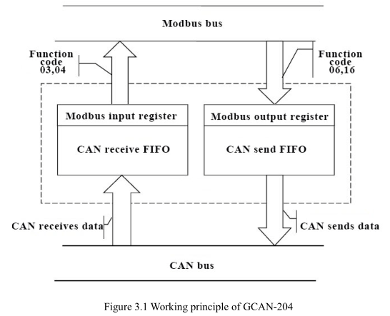
The working principle of GCAN-204, as shown in figure 3.1.
3.1 The structure of CAN- - Bus
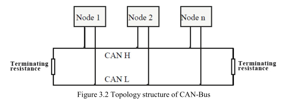
CAN-Bus connection, as shown in figure 3.2.
3.2 Termination resistor
CAN-Bus requires two 120Ω termination resistors in the furthest of the two terminals, as shown in figure 3.3.
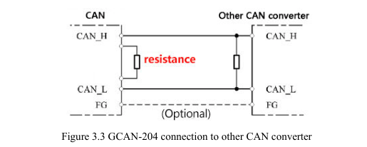
Please note: You should connect the two ends of the resistor to CAN_L and CAN_H respectively.
3.3 Indicator light
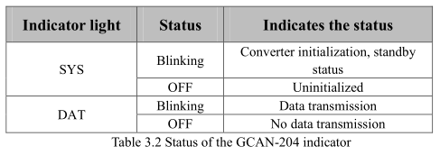
GCAN-204 converter has one SYS indicator, one DAT indicator that can indicate the converter status. More functions are shown in table 3.2.
The working principle of GCAN-204, as shown in figure 3.1.
3.1 The structure of CAN- - Bus
CAN-Bus connection, as shown in figure 3.2.
3.2 Termination resistor
CAN-Bus requires two 120Ω termination resistors in the furthest of the two terminals, as shown in figure 3.3.
Please note: You should connect the two ends of the resistor to CAN_L and CAN_H respectively.
3.3 Indicator light
GCAN-204 converter has one SYS indicator, one DAT indicator that can indicate the converter status. More functions are shown in table 3.2.
