Configuration Instructions for Modbus/RTU-CAN converter_GCAN
4. Configuration instructions
4.1 Configuration to prepare
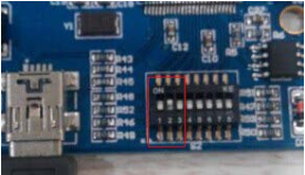
Open the shell of the converter, find the DIP switch shown below, turn switch 2 to "ON", then connected to the power supply, you can enter the configuration mode.
Please note: GCAN-204 uses RS485 interface to configure, do not connect the "Mini USB" interface.
4.2 Connect the software
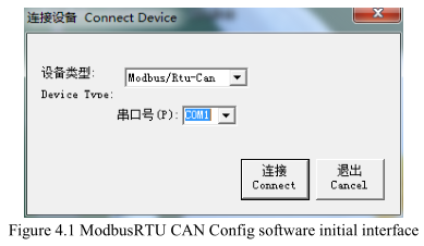
When GCAN-204 enters the configuration mode, use a RS485 line to connects to PC. Open the "ModbusRTU CAN Config" software, then configure the parameters. The software interface is shown in figure 4.1.
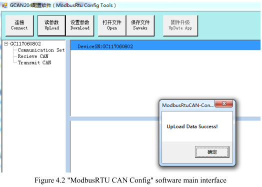
Select the serial number, click "Connect". After setting up the connection, click "读参数 Upload" to read the current configuration parameters, as shown in figure 4. 2.
Please note: At this point the converter has been connected with the PC, please do not click "Connect" repeatedly.
4.3 Configure parameter
Click on "Communication Set".
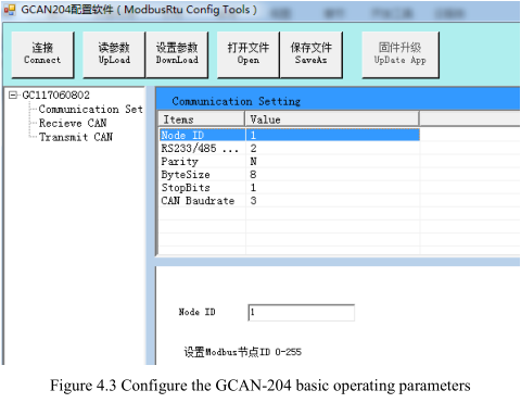
In this interface, you can set:
Node ID: The ID of the Modbus node
Parity: Odd parity or even parity
Byte Size: The length of the data
Stop Bits: Stop the number of bits
RS232 / 485 Baud: Modbus RTU baud rate
CAN Baudrate: CAN-Bus baud rate
Factory setting: Modbus RTU side baud rate is 57600bps, CAN baud rate is 250Kbps.
4.4 Configure mapping table
Press "Add" to add data. "Receive CAN" Modbus address: 0x00-0x7F, Modbus address of Transmit CAN: 0x100-0x17F.
4.4.1 Receive CAN
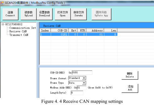
Click "Receive CAN", as shown in figure 4.4
COB-ID: Sets the frame ID of the CAN-Bus
Frame Format: Sets the frame format (Standard / Extended)
Frame Type: Sets the frame type (Data / RTR)
Modbus Address: Modbus register first address setting
Length: CAN frame data length, the maximum value of 8
4.4.2 Transmit CAN
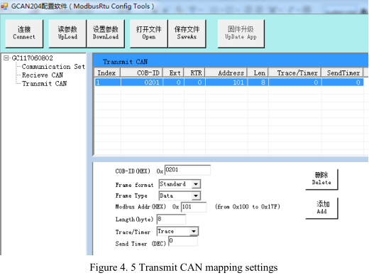
Click "Transmit CAN" to add data mapping group, as shown in figure 4. 5.
COB-ID: Sets the frame ID to be forwarded to CAN-Bus data
Frame Format: Sets the frame format (Standard / Extended)
Frame Type: Sets the frame type (Data / RTR)
Modbus Address: Sets the Modbus terminal register’s first address
Length: CAN frame data length, the maximum value is 8.
Set "Trace" or "Timer".
Trace: When a Modbus master sends a Modbus address data with a 06 instruction, if
the data changes, it will trigger the corresponding CAN data transmission.
Timer: You can set the interval time, send CAN data circularly. It sets the interval in
the "Send Timer", and enter the decimal number. The unit is milliseconds. For
example, “enter 1000” can sent at intervals of 1000ms.
4.5 Download parameters
After the configuration is completed, click on"设置参数 Download", download the configuration data to the converter's "FLASH". If the download actions is unsuccessful, please download it again.
Please note: After the data is downloaded successfully, you need to set the No. 2 DIP switch to "OFF", and then restart the converter, to enable the new configuration.
4.6 Save parameters
Save the configuration, click "保存文件 SaveAs" to save the parameters to the PC. Then the file can be used many times.
4.1 Configuration to prepare
Open the shell of the converter, find the DIP switch shown below, turn switch 2 to "ON", then connected to the power supply, you can enter the configuration mode.
Please note: GCAN-204 uses RS485 interface to configure, do not connect the "Mini USB" interface.

4.2 Connect the software
When GCAN-204 enters the configuration mode, use a RS485 line to connects to PC. Open the "ModbusRTU CAN Config" software, then configure the parameters. The software interface is shown in figure 4.1.

Select the serial number, click "Connect". After setting up the connection, click "读参数 Upload" to read the current configuration parameters, as shown in figure 4. 2.
Please note: At this point the converter has been connected with the PC, please do not click "Connect" repeatedly.

4.3 Configure parameter
Click on "Communication Set".

Node ID: The ID of the Modbus node
Parity: Odd parity or even parity
Byte Size: The length of the data
Stop Bits: Stop the number of bits
RS232 / 485 Baud: Modbus RTU baud rate
CAN Baudrate: CAN-Bus baud rate
Factory setting: Modbus RTU side baud rate is 57600bps, CAN baud rate is 250Kbps.
4.4 Configure mapping table
Press "Add" to add data. "Receive CAN" Modbus address: 0x00-0x7F, Modbus address of Transmit CAN: 0x100-0x17F.
4.4.1 Receive CAN
Click "Receive CAN", as shown in figure 4.4
COB-ID: Sets the frame ID of the CAN-Bus
Frame Format: Sets the frame format (Standard / Extended)
Frame Type: Sets the frame type (Data / RTR)
Modbus Address: Modbus register first address setting
Length: CAN frame data length, the maximum value of 8

4.4.2 Transmit CAN
Click "Transmit CAN" to add data mapping group, as shown in figure 4. 5.
COB-ID: Sets the frame ID to be forwarded to CAN-Bus data
Frame Format: Sets the frame format (Standard / Extended)
Frame Type: Sets the frame type (Data / RTR)
Modbus Address: Sets the Modbus terminal register’s first address
Length: CAN frame data length, the maximum value is 8.
Set "Trace" or "Timer".
Trace: When a Modbus master sends a Modbus address data with a 06 instruction, if
the data changes, it will trigger the corresponding CAN data transmission.
Timer: You can set the interval time, send CAN data circularly. It sets the interval in
the "Send Timer", and enter the decimal number. The unit is milliseconds. For
example, “enter 1000” can sent at intervals of 1000ms.
4.5 Download parameters
After the configuration is completed, click on"设置参数 Download", download the configuration data to the converter's "FLASH". If the download actions is unsuccessful, please download it again.
Please note: After the data is downloaded successfully, you need to set the No. 2 DIP switch to "OFF", and then restart the converter, to enable the new configuration.

4.6 Save parameters
Save the configuration, click "保存文件 SaveAs" to save the parameters to the PC. Then the file can be used many times.


