Use Of Ethernet-CAN converter_GCAN
3. converter used
GCAN-202 converter uses a network cable to connect to PC, uses +9 ~ 30V DC power supply(recommended + 12V or + 24V power supply), uses the "CANet Config" software to configure.
3.1 Restore the factory settings
Default IP of GCAN-202 is 192.168.1.10, gateway is 255.255.255.0. If the user has modified the IP and forget it. By pressing the reset button, you can restore the factory settings.

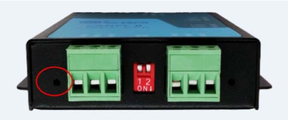
After GCAN-202 is powered on, you can find the reset button as shown above. Then press the button for about 5-6 seconds. When the indicator flashes, the system is restored successfully.
Please note: PC and GCAN-202 must be in the same network segment.
3.2 The structure of CAN-Bus
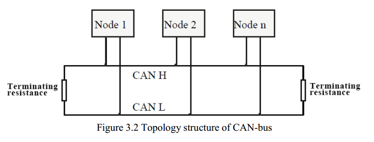
This is CAN-Bus connection, as shown in figure 3. 2.

3.3 Termination resistor
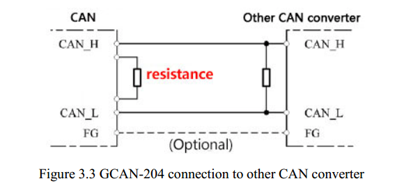
CAN-Bus requires two 120Ω termination resistors in the furthest of the two terminals, as shown in figure 3.3.

Please note: you should connect the two ends of the resistor to CAN_L and CAN_H respectively.
3.4 Indicator light
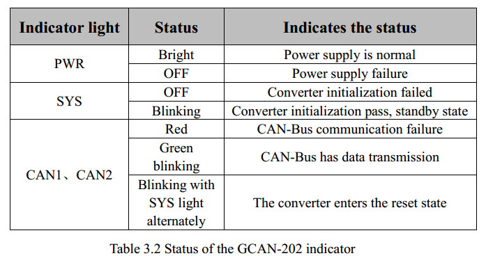
GCAN-202 converter has one PWR indicator, one SYS indicator, one LAN indicator, two CAN indicator, to indicate the converter status. More functions are shown in table 3.2.

GCAN-202 converter uses a network cable to connect to PC, uses +9 ~ 30V DC power supply(recommended + 12V or + 24V power supply), uses the "CANet Config" software to configure.
3.1 Restore the factory settings
Default IP of GCAN-202 is 192.168.1.10, gateway is 255.255.255.0. If the user has modified the IP and forget it. By pressing the reset button, you can restore the factory settings.

After GCAN-202 is powered on, you can find the reset button as shown above. Then press the button for about 5-6 seconds. When the indicator flashes, the system is restored successfully.
Please note: PC and GCAN-202 must be in the same network segment.
3.2 The structure of CAN-Bus
This is CAN-Bus connection, as shown in figure 3. 2.

3.3 Termination resistor
CAN-Bus requires two 120Ω termination resistors in the furthest of the two terminals, as shown in figure 3.3.

Please note: you should connect the two ends of the resistor to CAN_L and CAN_H respectively.
3.4 Indicator light
GCAN-202 converter has one PWR indicator, one SYS indicator, one LAN indicator, two CAN indicator, to indicate the converter status. More functions are shown in table 3.2.


