
Application Example of CANopen IO 8DI/8DO
5.3 PDO command
TPDO1 of GCAN-4055 is used to indicate the state of input and output. Each of them is represented by one byte. RPDO1 is used to change the state of digital output. It is controlled by one byte.
5.3.1 RPDO command(RPDO1, send by the master station)
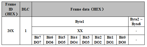
Users can send data using CANopen master station or manual simulation. You can set the output status of GCAN-4055 module. Frame ID is 0x200+Node ID(X). Length of the data is 1. The first byte of the frame data is used to set output state, each bit set to 1 represents output, 0 represents no output.
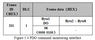
For example, the DO_3 state of the module is set to output, and the remaining DO state is no output. You can send the data as shown in the table below and figure 3 in figure 5.4.
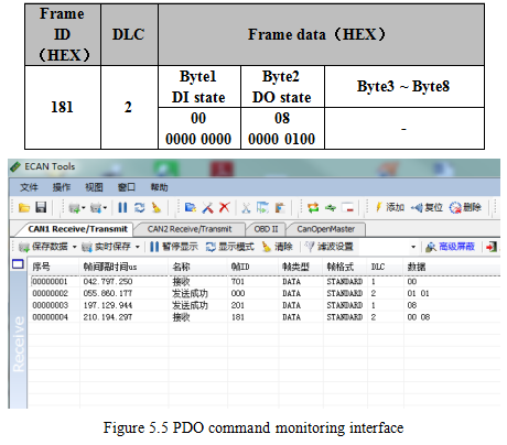
GCAN-4055 receive the data as shown in the table of the third data in figure 5.5.
5.3.2 TPDO command(TPDO1, send by GCAN-4055)
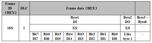
GCAN-4055 uses TPDO to send the current input and output status. Frame ID is 0x180 + Node ID (X). The data length is 2. The first byte is the input state, and the second byte is the output state. Each bit is 1 represents input/output, 0 represents no input/output. GCAN-4055 has two kinds of TPDO transmission modes. Trigger mode and circulation mode.
Default is trigger mode, in this mode, only when DI or DO changes, GCAN-4055 will send TPDO data.
In the circulation mode, GCAN-4055 sends out a TPDO data every 100ms(Cycle time can be changed). Show the state of DI and DO at that time.
For example, all DI state is no input, and the DO3 state is output, and the remaining DO states are no output. GCAN-4055 sends the data as shown in the table below and the fourth data in figure 5.5.
5.4 SDO command
The user can send the SDO instructions to modify the TPDO transmission mode of GCAN-4055 through the CANopen master station or manual simulation. There are two types of work modes that can be set - trigger mode (default) and circulation mode.
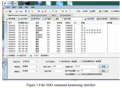
5.4.1 Circular pattern configuration
The circulation mode is shown in figure 5.6. After entering the circulation mode, GCAN-4055 sends TPDO to master station every once in a while.
Setting method:
① Get GCAN-4055 into the pre-operational state (see 5.2).
② Send a frame ID of 601 to GCAN-4055, frame data is 2F 00 18 02 FE 00 00 00. The frame ID of the reply of GCAN-4055 will be 581 after successful delivery, the frame data is 60 00 18 02 XX XX XX. This indicates that the change is successful.
③ Send the Start remote node (see 5.2) to start the converter, GCAN-4055 sends one TPDO data every 100ms (by default). This is the success of the configuration circulation pattern.
Note: If you need to change the interval time of the circulation mode. After the second step, Send frame ID 601 to GCAN-4055. The frame data is 2F 00 20 01 XX 00 00 00. The red part is the change in the time interval(Hexadecimal), maximum FF, unit ms.
5.4.2 Trigger mode configuration specification (default mode)
The trigger mode is shown in figure 5.7, GCAN-4055 only sends TPDO to master station when IO is changed.
Setting method:
① Get the GCAN-4055 into the pre-operational state (see 5.2).
② Send the frame ID to the converter 601, and the frame data is 2F 00 18 02 FF 00 00 00. The frame ID of the module response will be 581 after the successful delivery, and the frame data will be 60 00 18 02 XX XX XX.
③ After setting success, send the start remote node (see 5.2) to start the converter. The converter only sends a TPDO data indicating that the configured circulation mode is successful.
Last:Connect to CANopen IO 8DI/8DO_GCAN
Next:No more
