Connect to CANopen IO 8DI/8DO_GCAN
4 Connect to converter
4.1 Power supply
GCAN-4055 support +9-30V DC power supply. We recommend to use 12V or 24V DC voltage-stabilized power supply.
4.2 Connect to CAN-Bus
In practical use, connecting the CAN_H to CAN_H and CAN_L to CAN_L, then communication can be realized.
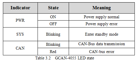
Note: The CAN-Bus network adopts topological structure, only the two furthest terminal need to connect 120Ω terminal resistance between CAN_H and CAN_L. See figure 3.2.
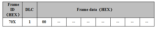
4.3 System LED
GCAN-4055 has one PWR indicator, one COM indicator, one CAN indicator to indicate the converter status. More functions are shown in table 3.2.
5 Application example
Note: All slave station in this chapter are set to 1.
This chapter will use USBCAN-II Pro converter and ECANTools software to receive and send CAN-Bus data.
You are welcome to purchase it through contact information in the last page of this manual. You can connect USBCAN-II Pro converter CAN1 channel to the CAN-Bus channel of Gcan-4055. Then open the ECANTools software and select the correct baud rate.
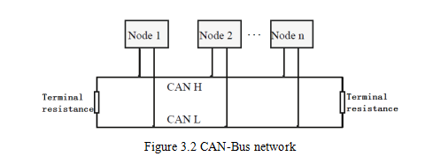
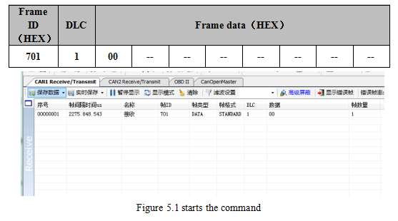
5.1 Start command
GCAN-4055 will send one frame to master station.
Frame ID is 0x700+Node ID(X). Length of the data is 1. Frame data is 0x00.
For example, GCAN-4055 will automatically send a data when it starts.
USBCAN-II Pro converter can receive this data and display it, as shown in figure 5.1.
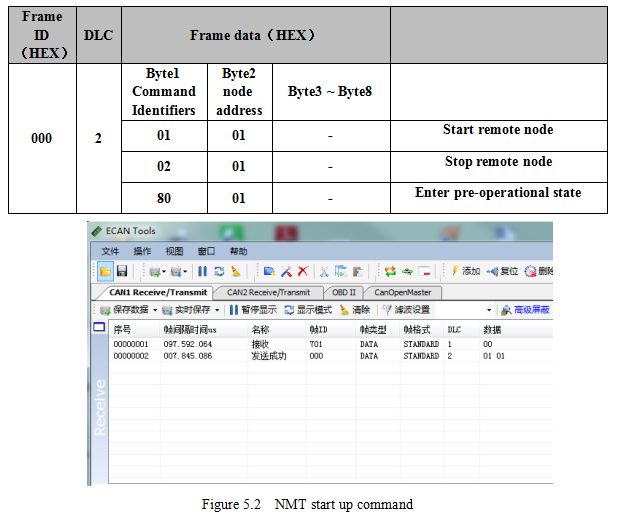
5.2 NMT command(Network management)
Users can use the NMT command of CANopen master station or manually simulate the CANopen protocol to control the GCAN-4055 to start or stop. Manual simulation of CANopen protocol start up module data is shown in the following table.