
Adapter in use_GCAN
3. Adapter in use
3.1 Correction system time
GCAN-401 has integrated system clock, system clock and file system can record data by date.
GCAN-401 will create folder every day named by date. Bus data will be automatically deposited in the corresponding folder.
GCAN-401 will create a new file per minute, data will saved to the corresponding file.
If GCAN-401 adapter’s system clock not real before use, user can adjust their own time by following methods.
1. Use an USB cable to connect the GCAN-401 and PC .(USB port in Figure 3.2)
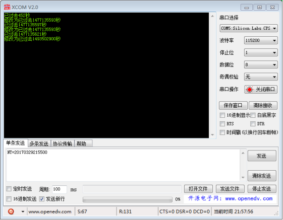
2. Use serial debugging assistant send your time to the adapter.
(serial port baud rate: 115200, data bits: 8, stop bit: 1, parity bit None, instruction is: "NT = XXX". For example: send "NT = 20170329215500", will amend the system time to March 29, 2017 21:55:00. Please note that, send and receive in ASCII and select "send new line", don't choose "hex".)
3.2 CAN bus configuration
GCAN-401 adapter generally require users to set the CAN-Bus communication parameters according to the actual demand before use.
3.2.1 CAN-bus baud rate configuration
GCAN-401 can support some commonly used baud rate between 10K~1000K. Baud rate can be set by code switch, the code switch position as shown in figure 3.2.
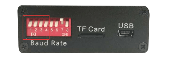
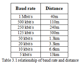
The code switch "1, 2, 3, 4" can set the CAN-Bus baud rate, and the other switch (5, 6, 8) has a special definition, the default side down, please do not arbitrarily set. Dial the code switch down the default is 0, each baud rate as shown in the table 3.1.
Note: Modify the baud rate must power down
3.2.2 CAN-Bus terminal resistance configuration
GCAN-401 has been integrated internal 120Ω terminal resistor, users can choose whether access through dial the code switch.
3.3 Connect to CAN
CANCOM adapter connect to CAN-Bus as chapter 2.2, CAN_H to CAN_H, CAN_L to CAN_L.
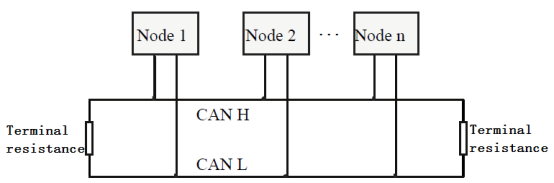
The CAN-bus network adopts topological structure, only the two furthest terminal need to connect 120Ω terminal resistance between CAN_H and CAN_L. For branch connection, its length should not be more than 3m. CAN-bus nodes connection as shown in figure 3.1
Note: the CAN-bus cable can use ordinary twisted-pair cable, shielded twisted-pair cable. Theory of the maximum communication distance depends on the bus baud rate, Their relationship as shown in the Table 3.1.
3.4 CAN-Bus terminal resistance
In order to improving the communication reliability and eliminating CAN-bus terminal reflection, the two furthest terminal need to connect terminal resistance between CAN_H and CAN_L as shown in figure 3.2. Terminal resistance values determined by the characteristic impedance of the cables. Such as, the characteristic impedance is 120Ω.
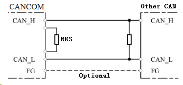
Note: CANCOM adapter not integrated 120Ω terminal resistance, users must connect it if necessary.
3.5 System LED
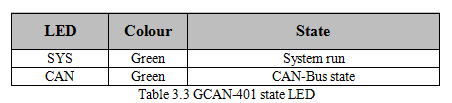
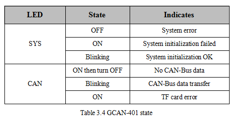
GCAN-401 adapter with one SYS indicator, one CAN indicator to indicate the adapter status. More functions are shown in table 3.3 and 3.4.
When GCAN-401 adapter power on, SYS LED blinking, indicates the adapter has power supply, the system is initialized; Otherwise, a system power failure or system errors has exist.
When power up, CAN LED on indicates TF card error.
When CAN LED on and then off, indicates TF card work fine .
When adapter receive data, CAN LED will blinking.
3.1 Correction system time
GCAN-401 has integrated system clock, system clock and file system can record data by date.
GCAN-401 will create folder every day named by date. Bus data will be automatically deposited in the corresponding folder.
GCAN-401 will create a new file per minute, data will saved to the corresponding file.
If GCAN-401 adapter’s system clock not real before use, user can adjust their own time by following methods.
1. Use an USB cable to connect the GCAN-401 and PC .(USB port in Figure 3.2)
2. Use serial debugging assistant send your time to the adapter.
(serial port baud rate: 115200, data bits: 8, stop bit: 1, parity bit None, instruction is: "NT = XXX". For example: send "NT = 20170329215500", will amend the system time to March 29, 2017 21:55:00. Please note that, send and receive in ASCII and select "send new line", don't choose "hex".)
Figure 3.1 GCAN-401 correction system time interface
3.2 CAN bus configuration
GCAN-401 adapter generally require users to set the CAN-Bus communication parameters according to the actual demand before use.
3.2.1 CAN-bus baud rate configuration
GCAN-401 can support some commonly used baud rate between 10K~1000K. Baud rate can be set by code switch, the code switch position as shown in figure 3.2.
Figure 3.2 GCAN-401 profile
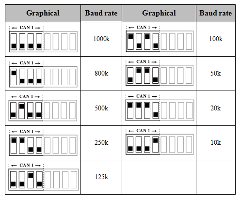
The code switch "1, 2, 3, 4" can set the CAN-Bus baud rate, and the other switch (5, 6, 8) has a special definition, the default side down, please do not arbitrarily set. Dial the code switch down the default is 0, each baud rate as shown in the table 3.1.
Note: Modify the baud rate must power down
Table 3.1 GCAN-401 Baud rate configuration chart
3.2.2 CAN-Bus terminal resistance configuration
GCAN-401 has been integrated internal 120Ω terminal resistor, users can choose whether access through dial the code switch.
3.3 Connect to CAN
CANCOM adapter connect to CAN-Bus as chapter 2.2, CAN_H to CAN_H, CAN_L to CAN_L.
The CAN-bus network adopts topological structure, only the two furthest terminal need to connect 120Ω terminal resistance between CAN_H and CAN_L. For branch connection, its length should not be more than 3m. CAN-bus nodes connection as shown in figure 3.1
Note: the CAN-bus cable can use ordinary twisted-pair cable, shielded twisted-pair cable. Theory of the maximum communication distance depends on the bus baud rate, Their relationship as shown in the Table 3.1.
3.4 CAN-Bus terminal resistance
In order to improving the communication reliability and eliminating CAN-bus terminal reflection, the two furthest terminal need to connect terminal resistance between CAN_H and CAN_L as shown in figure 3.2. Terminal resistance values determined by the characteristic impedance of the cables. Such as, the characteristic impedance is 120Ω.
Note: CANCOM adapter not integrated 120Ω terminal resistance, users must connect it if necessary.
3.5 System LED
GCAN-401 adapter with one SYS indicator, one CAN indicator to indicate the adapter status. More functions are shown in table 3.3 and 3.4.
When GCAN-401 adapter power on, SYS LED blinking, indicates the adapter has power supply, the system is initialized; Otherwise, a system power failure or system errors has exist.
When power up, CAN LED on indicates TF card error.
When CAN LED on and then off, indicates TF card work fine .
When adapter receive data, CAN LED will blinking.
