
CAN-Bus relay converter Usage Instructions_GCAN
3. converter in use
3.1 Connect to USB
When driver and software have been installed, connect the converter to the USB interface, a new USBCAN device named "GC - Tech USBCAN Device" can be found in the PC Device manager.
3.2 Connect to CAN
GCAN-206 converter connect to CAN-Bus as chapter 2.3, CAN_H to CAN_H, CAN_L to CAN_L.
The CAN bus network adopts topological structure, only the two furthest terminal need to connect 120Ω terminal resistance between CAN_H and CAN_L. For branch connection, its length should not be more than 3m. CAN-bus nodes connection as shown in figure 3.1
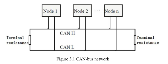
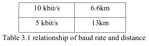
Note: the CAN-bus cable can use ordinary twisted-pair cable, shielded twisted-pair cable. Theory of the maximum communication distance depends on the bus baud rate, Their relationship as shown in the Table 3.1.

3.3 CAN-Bus terminal resistance
In order to improving the communication reliability and eliminating CAN-bus terminal reflection, the two furthest terminal need to connect terminal resistance between CAN_H and CAN_L as shown in figure 3.2. Terminal resistance values determined by the characteristic impedance of the cables. Such as, the characteristic impedance is 120Ω.
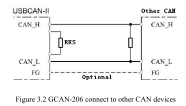
NOTE: GCAN-206 doesn't have integrated 120Ω terminal resistance, and need the customer to add it.
3.4 System LED
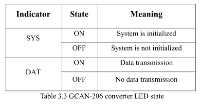
GCAN-206 converter with one SYS indicator to indicate the converter status. One DAT indicator to indicate data transmission. More functions are shown in table 3.2 and 3.3.
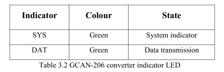 When GCAN-206 converter power on, SYS light, indicates the converter has power supply, the system is initialized. Otherwise, a system power failure or system errors has exist. When CAN-Bus1 or CAN-Bus2 data transceiver, DAT will blinking.
3.1 Connect to USB
When driver and software have been installed, connect the converter to the USB interface, a new USBCAN device named "GC - Tech USBCAN Device" can be found in the PC Device manager.
3.2 Connect to CAN
GCAN-206 converter connect to CAN-Bus as chapter 2.3, CAN_H to CAN_H, CAN_L to CAN_L.
The CAN bus network adopts topological structure, only the two furthest terminal need to connect 120Ω terminal resistance between CAN_H and CAN_L. For branch connection, its length should not be more than 3m. CAN-bus nodes connection as shown in figure 3.1
Note: the CAN-bus cable can use ordinary twisted-pair cable, shielded twisted-pair cable. Theory of the maximum communication distance depends on the bus baud rate, Their relationship as shown in the Table 3.1.
3.3 CAN-Bus terminal resistance
In order to improving the communication reliability and eliminating CAN-bus terminal reflection, the two furthest terminal need to connect terminal resistance between CAN_H and CAN_L as shown in figure 3.2. Terminal resistance values determined by the characteristic impedance of the cables. Such as, the characteristic impedance is 120Ω.
NOTE: GCAN-206 doesn't have integrated 120Ω terminal resistance, and need the customer to add it.
3.4 System LED
GCAN-206 converter with one SYS indicator to indicate the converter status. One DAT indicator to indicate data transmission. More functions are shown in table 3.2 and 3.3.
