Installation of CAN-Bus relay converter_GCAN
2. Installation
2.1 Driver and software installation
2.1.1 Install driver and software
ECAN Tools has been integrated hardware driver installation program, users can directly install ECAN Tools.
If you only need to install the driver, please enter the “driver” folder, select the installation file that corresponds to the system type. (“DriverSetup.exe” for 32-bit. “DriverSetup64.exe” for 64-bit)
2.1.2 Uninstall driver and software
Users can run the DriverSetup.exe/ DriverSetup64.exe and click "Uninstall" button to uninstall the installed device driver.
2.2 Connect to PC
The converter can be connected directly to a PC using a USB cable, if the USB power supply is insufficient, you need to use external power supply.
2.3 Fixation of converter
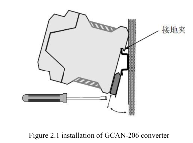
The installation method of the GCAN-206 converter is shown in figure 2.1.
Use a screwdriver to help install the module to the DIN guide.

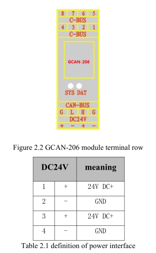
The wiring terminals of the GCAN-206 converter are shown in figure 2.2.
The power terminal interface definition is shown in table 2.1.

2.4 Connect to CAN-Bus
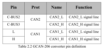
GCAN-206 has two CAN-Bus by two 4 Pin plug type terminal leads, these CAN-Bus channels can connect two CAN-Bus network or devices. Terminal pin definition as Table 2.2 below.

Note: In practical use, most of the time just connected the CAN_H to CAN_H and CAN_Lconnected to CAN_Lthen communication can be realized
2.1 Driver and software installation
2.1.1 Install driver and software
ECAN Tools has been integrated hardware driver installation program, users can directly install ECAN Tools.
If you only need to install the driver, please enter the “driver” folder, select the installation file that corresponds to the system type. (“DriverSetup.exe” for 32-bit. “DriverSetup64.exe” for 64-bit)
2.1.2 Uninstall driver and software
Users can run the DriverSetup.exe/ DriverSetup64.exe and click "Uninstall" button to uninstall the installed device driver.
2.2 Connect to PC
The converter can be connected directly to a PC using a USB cable, if the USB power supply is insufficient, you need to use external power supply.
2.3 Fixation of converter
The installation method of the GCAN-206 converter is shown in figure 2.1.
Use a screwdriver to help install the module to the DIN guide.

The wiring terminals of the GCAN-206 converter are shown in figure 2.2.
The power terminal interface definition is shown in table 2.1.

2.4 Connect to CAN-Bus
GCAN-206 has two CAN-Bus by two 4 Pin plug type terminal leads, these CAN-Bus channels can connect two CAN-Bus network or devices. Terminal pin definition as Table 2.2 below.

Note: In practical use, most of the time just connected the CAN_H to CAN_H and CAN_Lconnected to CAN_Lthen communication can be realized


