
The Connection of Ethernet-CANopen slave converter_GCAN
3. Connection and use
3.1 Configure with PC connections
The GCAN-302 converter uses a 24V DC power supply. By using the "TCP-CANopen Config" software, the GCAN-302 converter can configure the working model and the parameter. GCAN-302 only supports communication between TCP to CANopen, other protocols are not supported.
3.1.1 Restore the factory settings
GCAN-302 converter factory IP: 192.168.1.10. If users have changed the IP and forgot it, users can operate the DIP switch to reset the parameters.
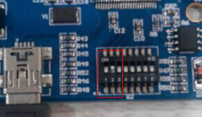
Operation method: first open the converter's shell and find the switch shown in Figure 3.1. Second switch the No. 2 to "ON", then supply the power, waiting for 3 seconds. After the "SYS" indicator flashing, turn off the power and switch back to "OFF". Now, the converter has been restored to the factory default state, and set the system factory to IP: 192.168.1.10.
Please note: after the converter has been reset, all parameter settings and mapping table settings will be cleared. Please be careful.
3.2 Connect to Ethernet
The Ethernet interface of the GCAN-302 converter integrates a 10 / 100M adaptive Ethernet chip. The converter conforms to the Ethernet standard protocol specification.
3.3 Connect to CAN-Bus
CAN-Bus connection is shown in figure 3.2.
3.4 Termination resistor
CAN-Bus requires two 120Ω termination resistors in the furthest of the two terminals, as shown in figure 3.3.
Please note: You should connect the two ends of the resistor to CAN_L and CAN_H respectively.
3.5 System LED
GCAN-302 converter has one SYS indicator, one DAT indicator. More functions are shown in table 3.2.
After power on the converter, the SYS indicator light indicates that power is being supplied and the system is initializing; otherwise, it indicates power failure or an error occurred.
If the bus has data transmission, DAT indicator will flash.
3.1 Configure with PC connections
The GCAN-302 converter uses a 24V DC power supply. By using the "TCP-CANopen Config" software, the GCAN-302 converter can configure the working model and the parameter. GCAN-302 only supports communication between TCP to CANopen, other protocols are not supported.
3.1.1 Restore the factory settings
GCAN-302 converter factory IP: 192.168.1.10. If users have changed the IP and forgot it, users can operate the DIP switch to reset the parameters.
Figure 3.1 The switch of GCAN-302
Operation method: first open the converter's shell and find the switch shown in Figure 3.1. Second switch the No. 2 to "ON", then supply the power, waiting for 3 seconds. After the "SYS" indicator flashing, turn off the power and switch back to "OFF". Now, the converter has been restored to the factory default state, and set the system factory to IP: 192.168.1.10.
Please note: after the converter has been reset, all parameter settings and mapping table settings will be cleared. Please be careful.
3.2 Connect to Ethernet
The Ethernet interface of the GCAN-302 converter integrates a 10 / 100M adaptive Ethernet chip. The converter conforms to the Ethernet standard protocol specification.
3.3 Connect to CAN-Bus
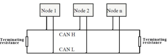
CAN-Bus connection is shown in figure 3.2.
Figure 3.2 Topology structure of CAN-Bus
3.4 Termination resistor
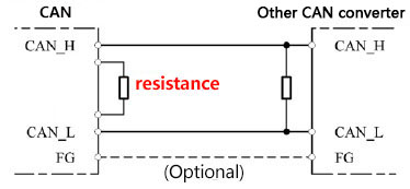
CAN-Bus requires two 120Ω termination resistors in the furthest of the two terminals, as shown in figure 3.3.
Figure 3.3 GCAN-302 connection to other CAN converter
Please note: You should connect the two ends of the resistor to CAN_L and CAN_H respectively.
3.5 System LED
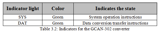
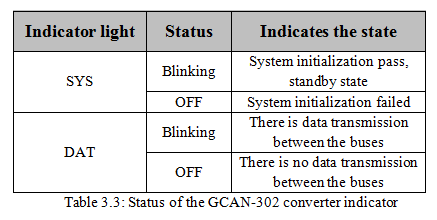
GCAN-302 converter has one SYS indicator, one DAT indicator. More functions are shown in table 3.2.
After power on the converter, the SYS indicator light indicates that power is being supplied and the system is initializing; otherwise, it indicates power failure or an error occurred.
If the bus has data transmission, DAT indicator will flash.
