
Introduce The Product Of 232/485-CAN converter_GCAN
1 Introduction
1.1 Overview
The GCAN-201 converter has integrated one standard CAN-Bus interface, one Serial-Bus interface (RS232 or RS485). GCAN-201 converter can build a connection between Serial-Bus and CAN-Bus. With this converter, equipment that used Serial-Bus can connect to CAN-Bus without changing the hardware structure, this makes multi-Bus interconnection very flexible, and extends the application scope of CAN-Bus.
1.2 Properties at a glance
Standard serial port level, RS232 model or RS485 model can switch by software
Conversion direction can be set to: CAN-Serial, CAN-Serial, CAN-Serial
Serial Bus baud rate range from 600bps to 115200bps
CAN-Bus supports CAN2.0A and CAN2.0B frame format, conform to ISO/DIS 11898 standards
CAN-Bus baud rates range from 5Kbps to 1Mbps
CAN-Bus interface with electrical isolation
CAN-Bus isolation module insulation voltage: DC 1500V
Power supply: 9~30V(20mA, 24V DC)
Installation method: DIN guide rail
Working temperature range from -40 to 85 °C
Size: (L)112mm * (W)70mm * (H)25mm
2 Installation
2.1 Connect to PC
The converter can be connected directly to a PC using an USB to RS232 cable. If PC have RS232 port, using RS232 directly is also possible.
2.2 Connect to CAN-Bus
In practical use, connecting the CAN_H to CAN_H and CAN_L to CAN_L, then communication can be realized.
2.3 Interface definition
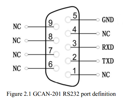
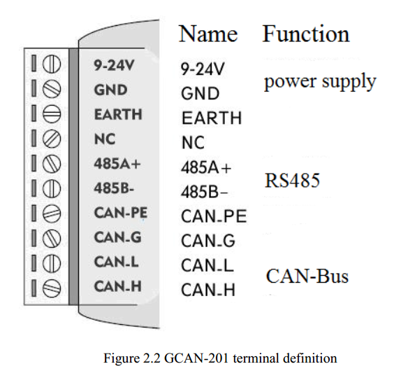
GCAN-201 converter port definition as shown in figure 2.1 and figure 2.2, using the terminal and the RS232 port, for industrial field application.
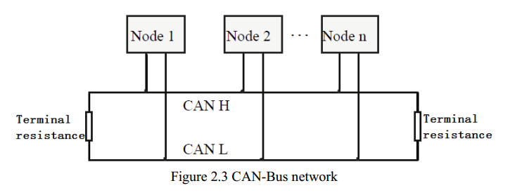
Note: The CAN-Bus network adopts topological structure, only the two furthest terminal need to connect 120Ω terminal resistance between CAN_H and CAN_L. For branch connection, its length should not be more than 3 meters. CAN-Bus nodes connection as shown in figure 2.3.
2.4 System LED
GCAN-201 converter with one PWR indicator, one COM indicator, one CAN indicator to indicate the converter status. More functions are shown in table 2.1.
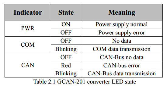
If PWR indicator lights up, it indicates that you plug GCAN-201 converter into an electricity supply, and the system is initialized.
Otherwise, a system power failure or system error has exist.
When Serial-bus data is being transmitted, COM indicator will blinking.
When CAN-bus data is being transmitted, CAN indicator will blinking in green.
If CAN error occurs, CAN indicator will turn red.
When COM and CAN indicator blink alternately, it means the adapter is in configuration mode
1.1 Overview
The GCAN-201 converter has integrated one standard CAN-Bus interface, one Serial-Bus interface (RS232 or RS485). GCAN-201 converter can build a connection between Serial-Bus and CAN-Bus. With this converter, equipment that used Serial-Bus can connect to CAN-Bus without changing the hardware structure, this makes multi-Bus interconnection very flexible, and extends the application scope of CAN-Bus.
1.2 Properties at a glance
Standard serial port level, RS232 model or RS485 model can switch by software
Conversion direction can be set to: CAN-Serial, CAN-Serial, CAN-Serial
Serial Bus baud rate range from 600bps to 115200bps
CAN-Bus supports CAN2.0A and CAN2.0B frame format, conform to ISO/DIS 11898 standards
CAN-Bus baud rates range from 5Kbps to 1Mbps
CAN-Bus interface with electrical isolation
CAN-Bus isolation module insulation voltage: DC 1500V
Power supply: 9~30V(20mA, 24V DC)
Installation method: DIN guide rail
Working temperature range from -40 to 85 °C
Size: (L)112mm * (W)70mm * (H)25mm
2 Installation
2.1 Connect to PC
The converter can be connected directly to a PC using an USB to RS232 cable. If PC have RS232 port, using RS232 directly is also possible.
2.2 Connect to CAN-Bus
In practical use, connecting the CAN_H to CAN_H and CAN_L to CAN_L, then communication can be realized.
2.3 Interface definition
GCAN-201 converter port definition as shown in figure 2.1 and figure 2.2, using the terminal and the RS232 port, for industrial field application.
Note: The CAN-Bus network adopts topological structure, only the two furthest terminal need to connect 120Ω terminal resistance between CAN_H and CAN_L. For branch connection, its length should not be more than 3 meters. CAN-Bus nodes connection as shown in figure 2.3.
2.4 System LED
GCAN-201 converter with one PWR indicator, one COM indicator, one CAN indicator to indicate the converter status. More functions are shown in table 2.1.
If PWR indicator lights up, it indicates that you plug GCAN-201 converter into an electricity supply, and the system is initialized.
Otherwise, a system power failure or system error has exist.
When Serial-bus data is being transmitted, COM indicator will blinking.
When CAN-bus data is being transmitted, CAN indicator will blinking in green.
If CAN error occurs, CAN indicator will turn red.
When COM and CAN indicator blink alternately, it means the adapter is in configuration mode
