CANopen IO 8DI/8DO


-
1.Overview
GCAN-4055(CANopen IO 8DI/8DO) is a CANopen converter which have one standard CANopen interface, 8 digital input channel and 8 digital output channel .
2.Properties at a glance
CAN-Bus supports CAN2.0A frame format, in accordance with ISO / DIS 11898 specification
CAN-Bus communication baud rate between 10Kbps ~ 1Mbps arbitrary programmable
CAN-Bus interface with electrical isolation, isolation module insulation voltage: DC 1500V
Use 9 ~ 30V DC power supply, 140mA (quiet state current: 40mA)
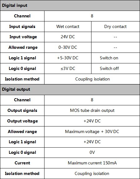
Number of digital inputs: 8 channels
Number of digital output channels: 8 channels
Digital input signal: support dry contact, wet contact input
Wet contact digital input high signal (digital 1): + 5V ~ 30V
Wet contact digital input Low level signal (digital 0): ≤ + 3V
Digital output signal: open collector output, the maximum load voltage +30 V, the
maximum leakage current of 150mA
DI, DO, CANopen interface using the terminal interface
Use the DIP switch to configure the module baud rate and node number
Can be used to connect the card rail connector, installed on the DIN rail
Operating temperature range: -40 ℃ ~ +85 ℃
Size: 121mm * 70mm * 26mm3.Examples
Note: All slave station in this chapter are set to 1.
This chapter will use USBCAN-II Pro converter and ECANTools software to receive and send CAN-Bus data.
You are welcome to purchase it through contact information in the last page of this manual. You can connect USBCAN-II Pro converter CAN1 channel to the CAN-Bus channel of Gcan-4055. Then open the ECANTools software and select the correct baud rate.3.1 Start command
GCAN-4055 will send one frame to master station.
Frame ID is 0x700+Node ID(X). Length of the data is 1. Frame data is 0x00.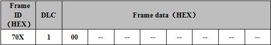
For example, GCAN-4055 will automatically send a data when it starts.
USBCAN-II Pro converter can receive this data and display it, as shown in figure 3.1.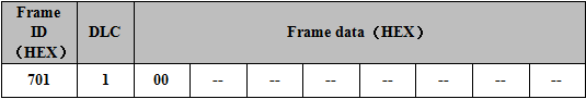

Figure 3.1 starts the command
3.2 NMT command(Network management)
Users can use the NMT command of CANopen master station or manually simulate the CANopen protocol to control the GCAN-4055 to start or stop. Manual simulation of CANopen protocol start up module data is shown in the following table.
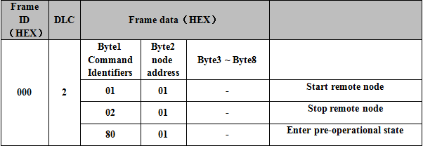
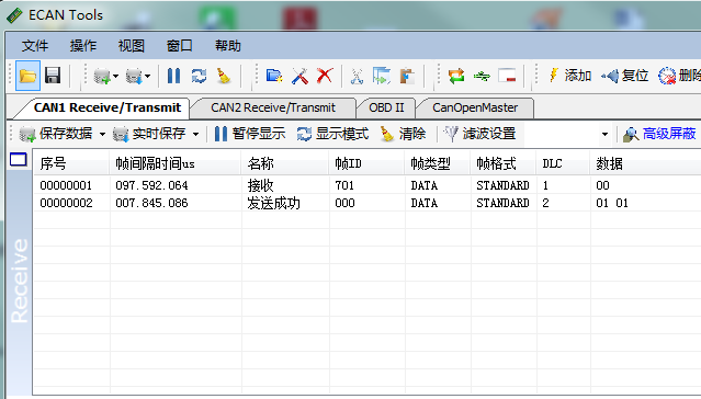
Figure 3.2 NMT start up command
3.3 PDO command
TPDO1 of GCAN-4055 is used to indicate the state of input and output. Each of them is represented by one byte. RPDO1 is used to change the state of digital output. It is controlled by one byte.
3.3.1 RPDO command(RPDO1, send by the master station)
Users can send data using CANopen master station or manual simulation. You can set the output status of GCAN-4055 module. Frame ID is 0x200+Node ID(X). Length of the data is 1. The first byte of the frame data is used to set output state, each bit set to 1 represents output, 0 represents no output.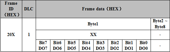
For example, the DO_3 state of the module is set to output, and the remaining DO state is no output. You can send the data as shown in the table below and figure 3 in figure 3.3.
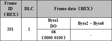
Figure 3.3 PDO command monitoring interface3.3.2 TPDO command(TPDO1, send by GCAN-4055)
GCAN-4055 uses TPDO to send the current input and output status. Frame ID is 0x180 + Node ID (X). The data length is 2. The first byte is the input state, and the second byte is the output state. Each bit is 1 represents input/output, 0 represents no input/output. GCAN-4055 has two kinds of TPDO transmission modes. Trigger mode and circulation mode.
Default is trigger mode, in this mode, only when DI or DO changes, GCAN-4055 will send TPDO data.
In the circulation mode, GCAN-4055 sends out a TPDO data every 100ms(Cycle time can be changed). Show the state of DI and DO at that time.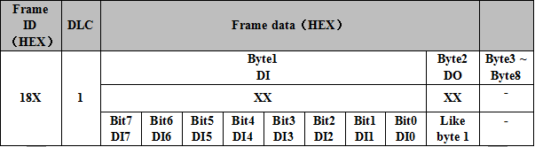
For example, all DI state is no input, and the DO3 state is output, and the remaining DO states are no output. GCAN-4055 sends the data as shown in the table below and the fourth data in figure 3.4.
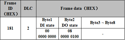
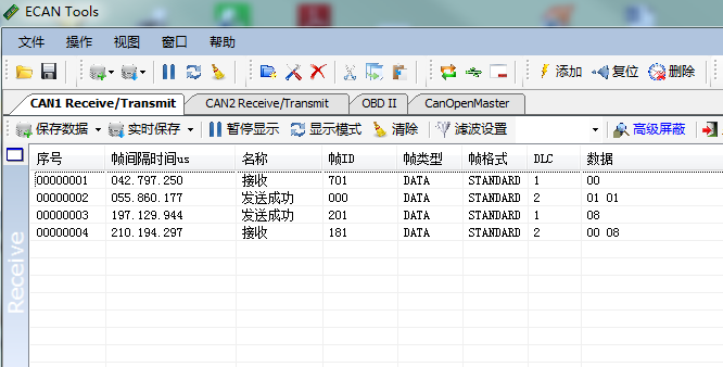
Figure 3.4 PDO command monitoring interface
3.4 SDO command
The user can send the SDO instructions to modify the TPDO transmission mode of GCAN-4055 through the CANopen master station or manual simulation. There are two types of work modes that can be set - trigger mode (default) and circulation mode.
3.4.1 Circular pattern configuration
The circulation mode is shown in figure 3.5. After entering the circulation mode, GCAN-4055 sends TPDO to master station every once in a while.
Setting method:
① Get GCAN-4055 into the pre-operational state (see 3.2).
② Send a frame ID of 601 to GCAN-4055, frame data is 2F 00 18 02 FE 00 00 00. The frame ID of the reply of GCAN-4055 will be 581 after successful delivery, the frame data is 60 00 18 02 XX XX XX. This indicates that the change is successful.
③ Send the Start remote node (see 3.2) to start the converter, GCAN-4055 sends one TPDO data every 100ms (by default). This is the success of the configuration circulation pattern.
Note: If you need to change the interval time of the circulation mode. After the second step, Send frame ID 601 to GCAN-4055. The frame data is 2F 00 20 01 XX 00 00 00. The red part is the change in the time interval(Hexadecimal), maximum FF, unit ms.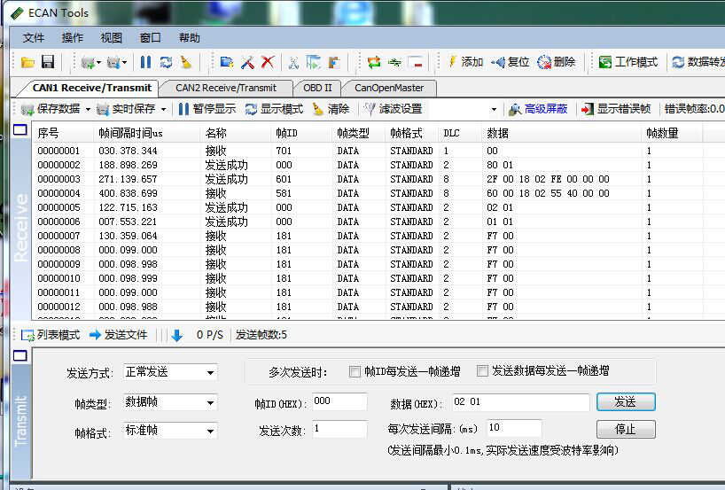
Figure 3.5 the SDO command monitoring interface
3.4.2 Trigger mode configuration specification (default mode)
The trigger mode is shown in figure 3.7, GCAN-4055 only sends TPDO to master station when IO is changed.
Setting method:
① Get the GCAN-4055 into the pre-operational state (see 3.2).
② Send the frame ID to the converter 601, and the frame data is 2F 00 18 02 FF 00 00 00. The frame ID of the module response will be 581 after the successful delivery, and the frame data will be 60 00 18 02 XX XX XX.
③ After setting success, send the start remote node (see 3.2) to start the converter. The converter only sends a TPDO data indicating that the configured circulation mode is successful.
4.Technical specifications

- CAN-Bus supports CAN2.0A frame format, in accordance with ISO / DIS 11898 specification
CAN-Bus communication baud rate between 10Kbps ~ 1Mbps arbitrary programmable
CAN-Bus interface with electrical isolation, isolation module insulation voltage: DC 1500V
Use 9 ~ 30V DC power supply, 140mA (quiet state current: 40mA)
Number of digital inputs: 8 channels
Number of digital output channels: 8 channels
Digital input signal: support dry contact, wet contact input
Wet contact digital input high signal (digital 1): + 5V ~ 30V
Wet contact digital input Low level signal (digital 0): ≤ + 3V
Digital output signal: open collector output, the maximum load voltage +30 V, the
maximum leakage current of 150mA
DI, DO, CANopen interface using the terminal interface
Use the DIP switch to configure the module baud rate and node number
Can be used to connect the card rail connector, installed on the DIN rail
Operating temperature range: -40 ℃ ~ +85 ℃
Size: 121mm * 70mm * 26mm
7 days no reason to return all goods.
All goods quality problems, one year free replacement machine.
Each sold products will provide professional engineers QQ, the national free 400 unified after-sales telephone for you to provide technical support at any time.-
GCAN-4055(CANopen IO 8DI8DO) converter
User Manual(Click to view)Please ask for more information to the Engineer.
E-mail:2881884588@qq.com